Op E R A T I N G pA N E l5. 3.
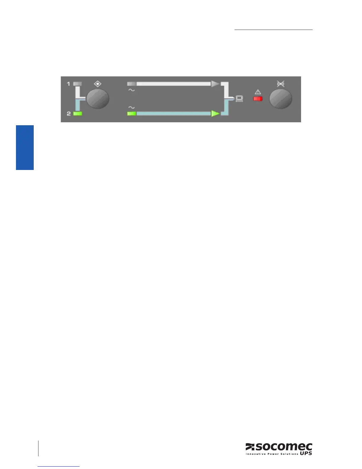
On the following scheme you can see the front panel of the ASYS.
Most functions of the ASYS are driven by an internal control device.
A priority setting can be made from the operating panel to prefer a mains source.
LEDs display the state of the relay group.
fE A T U R E S5. 4.
The ASYS provides redundant power supply to your load by switching it from pre-
ferred source to auxiliary source.
ASYS is compatible with UPS providing sinusoidal output (as well as direct main, gen-
erating set and all sinusoidal source)
Break Before Make (open transition) transfer mode –
Back feed protection (according EN62310-1). –
Complete protection for overload and short-circuit. (with accessible FUSE Hold- –
er).
Redundant power supply. (From input Source 1 and Source 2). –
AC source detection (voltage and current detection). –
Output detection (current detection). –
LED display. –
Dierent setting to adjust the voltage failure sensing level (+/- 12% ~ +/- 20%). see –
input/output table page 13
Protection: IP30. –
Buzzer inhibition –
Automatic rated frequency sensing –
 Loading...