EasyManuals Logo

socomec Asys 16 A Transfer System User Manual

socomec Asys 16 A Transfer System
19 pages
To Next Page IconTo Next Page
To Previous Page IconTo Previous Page
Page #11 background imageLoading...
Page #11 background image
ASYS
16 A Transfer System
ENGLISH
IOMASY160810-GB_00
7
EN V I R O N m E N T A l R E q U I S I T E S4. 7.
It is necessary to leave a minimum space of a few centimetres around right side, left
side and rear side to allow a ow of air and to provide access to the interface.
pR E S E N T A T I O N5.
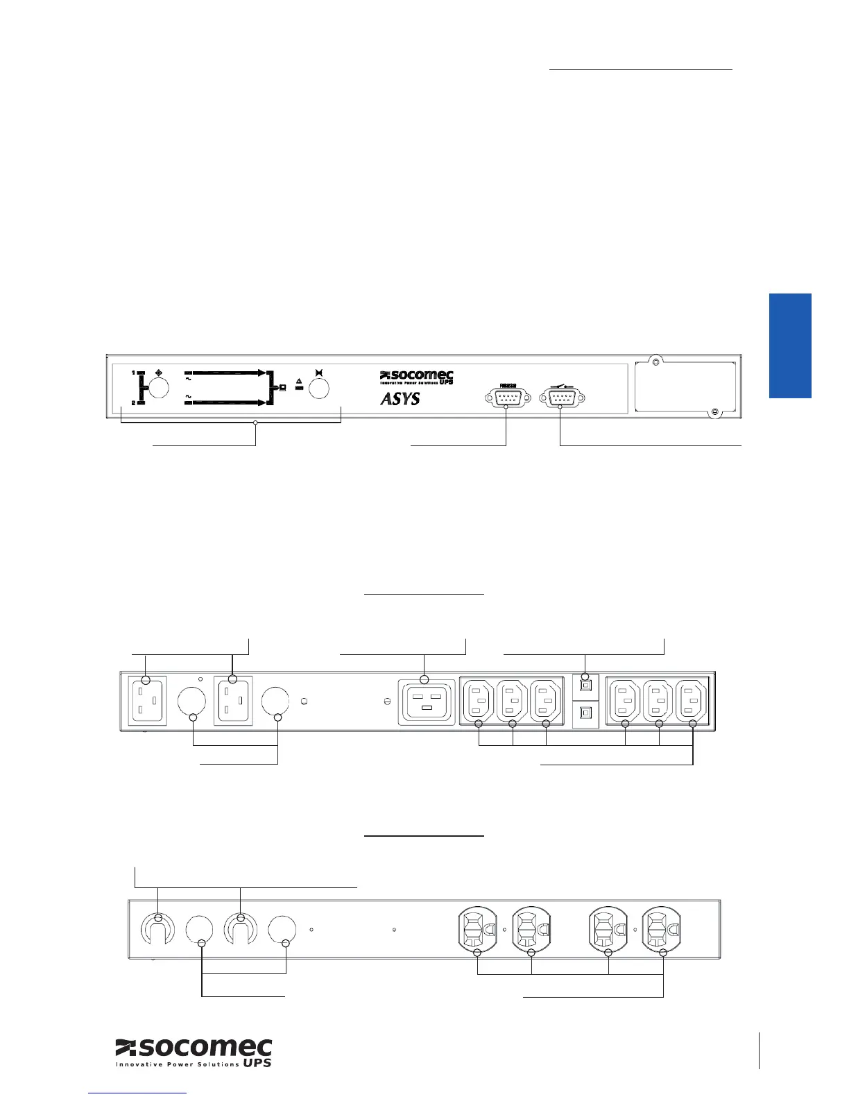
fR O N T pA N E l5. 1.
The front of the ASYS TRANSFER SWITCH with its LED display and interfaces:
RE A R pA N E l5. 2.
The back of the ASYS with its connectors, terminals and interfaces:
1 Output IEC320-C19
2 x 10A thermal protection
2 Input IEC 320 C20
2 x 3 Output IEC320-C132 Input Fuse
2 Input Fuse
2 Input Power cord AWG 12x3C / 20A
4 Output NEMA 5-20R
Op e r a t i n g p a n e l Se r v i c i n g a c c e S S
Dr y c O n t a c t (c O m m u n i c a t i O n a c c e S S )
ASyS 16A-230:
ASyS 16A-120:

Questions and Answers:

Question and Answer IconNeed help?

Do you have a question about the socomec Asys 16 A Transfer System and is the answer not in the manual?

socomec Asys 16 A Transfer System Specifications

General IconGeneral
Brandsocomec
ModelAsys 16 A Transfer System
CategorySwitch
LanguageEnglish

Related product manuals