Op E R A T I N G p R O C E D U R E S6.
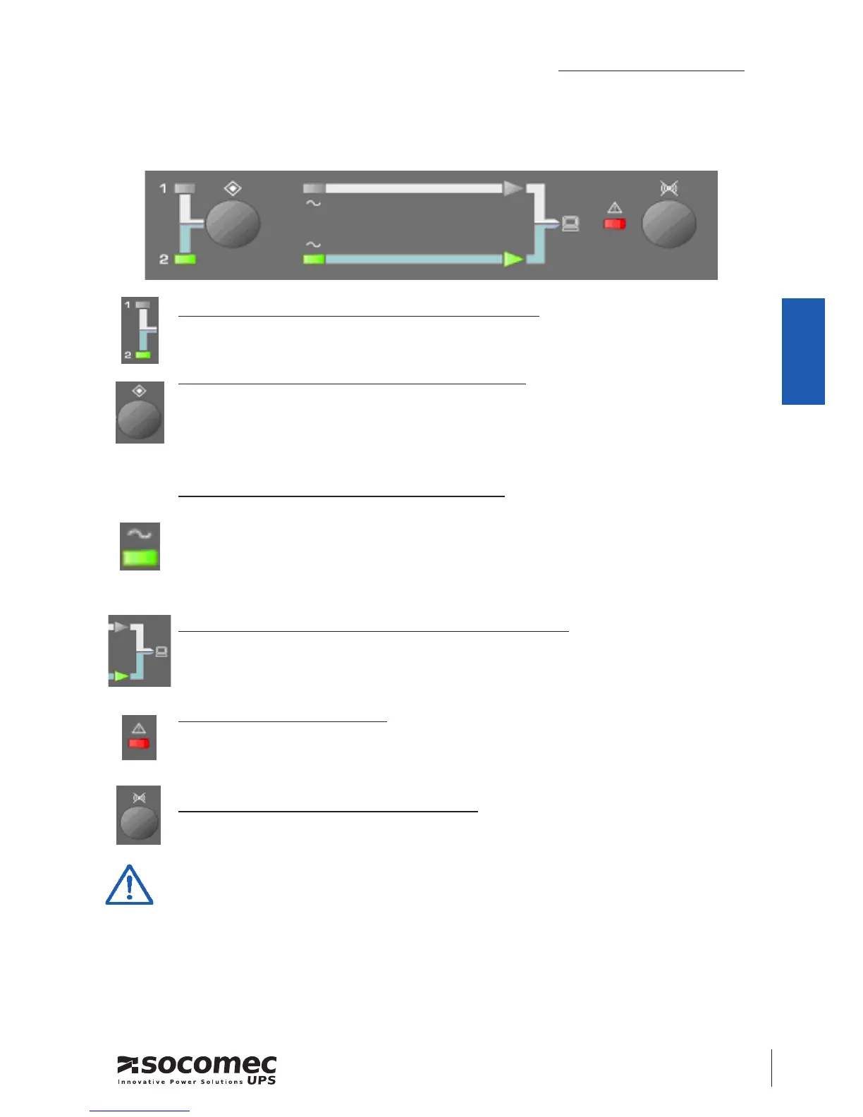
ASYS TRANSFER SWITCH panel display
LED 1 and LED 2 = Preferred Source indication:
Green LEDs indicate witch Input Source is selected as the preferred
LEFT BUTTON = change the Preferred Source:
source 1 is the preferred source on the factory setting,
the modication of the preferred source is done by pressing for 3 seconds
on this button
LED input line = status of the input source
Green LEDs indicate a correct source is present
LED ashing indicates an incorrect input, voltage or frequency is out of
range
LED o indicate the source is not present on the input
LED output power = input source feed to the load
Green LEDs on the line 1, the load is powered by input 1
Green LEDs on the line 2, the load is powered by input 2
FAULT LED = general alarm
Red LED indicates: Overload, Output short circuit; or Input Source Relay
fault
RIGHT BUTTON = buzzer acknowledge
push the button for 1 second to stop the buzzer
To cancel alarm, push simultaneously, the left and right buttons for
3 seconds
1. In normal operation, output power is always supplied from the selected preferred
source.
2. If the preferred source is out of range, ASYS will automatic transfer to the other
source until the preferred source is recovered within preset tolerance.
3. If both sources are out of range, the ASYS output will be stopped. (Load is not
powered under this condition)
 Loading...