MASTERYS IP+
40-60 kVA 3/1
ENGLISH
IOMMASIPXX07-GB 02
17
UNPACKING AND INSTALLATION
OF THE UNIT
3
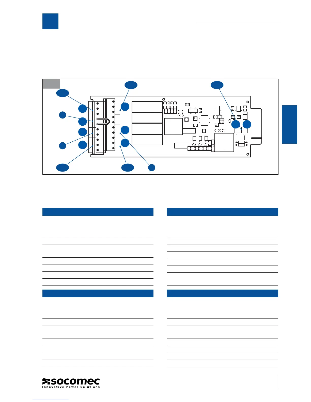
3.10 ADC CARD.
This card can be con gured to control up to four outputs that are normally closed or normally open and up
to three digital inputs. The card is inserted in one of two slots provided (refer to 3.5 “Identifying switching and
connection organs”) .
3.10-1
A
2
3
4
1
OUT
OUT
0 1 2 P3
C2 NO2 NC2 IN1- IN1+ IN3- IN3+ C3 NO3 NC3
C1 NO1 NC1 IN1- IN1+ IN2- IN2+ C4 NO4 NC4
OUT1
OUT2
DIP1 DIP2
IN3
OUT3
IN1
IN2
OUT4
Up to four operating modes can be selected using the two DIP switches 1 or 2.
• The lter level indicates:
1 immediate activation (1 seconds minimum communication time) - 2 10 s delay - 3 30 s delay.
Mode 1 - STANDARD con guration
Position IN/OUT Description Filter
dip1 dip2 level
OFF OFF Out 1 General Alarm 2
OFF OFF Out 2 Battery discharging 3
OFF OFF Out 3 Battery low or 2
imminent stop
OFF OFF Out 4 UPS on by-pass 2
OFF OFF In 1
*
E.S.D. 1
OFF OFF In 2 Supply from GenSet 1
OFF OFF In 3 Isolation controller 2
Mode 2 - POWER SAFE con guration
Position IN/OUT Description Filter
dip1 dip2 level
ON OFF Out 1 General Alarm 2
ON OFF Out 2 Power safe plug 1 2
ON OFF Out 3 Power safe plug 2 2
ON OFF Out 4 Power safe plug 3 2
ON OFF In 1
*
E.S.D. 1
ON OFF In 2 Supply from GenSet 1
ON OFF In 3 Management of 1
energy consuption
Mode 3 - SAFETY con guration
Position IN/OUT Description Filter
dip1 dip2 level
OFF ON Out 1 General Alarm 2
OFF ON Out 2 E.S.D. activation 1
OFF ON Out 3 Battery low or 2
imminent stop
OFF ON Out 4 E.S.D. activation 1
OFF ON In 1
*
E.S.D. 1
OFF ON In 2 External alarm A39 2
OFF ON In 3 External alarm A40 2
Mode 4 - ENVIRONMENTAL con guration
Position IN/OUT Description Filter
dip1 dip2 level
ON ON Out 1 General Alarm 2
ON ON Out 2 Over-heating 2
ON ON Out 3 Overload / 2
Loss of redundancy
ON ON Out 4 External alarm In2 2
ON ON In 1
*
E.S.D. 1
ON ON In 2 External alarm A39 2
ON ON In 3 External alarm A40 2
*
if the external E.S.D. button is not used, always insert a jumper to short circuit input IN 1 (Figure 10.1-1).
OUT1
IN2
OUT4
OUT2
OUT3
IN3
DIP1 2
IN1
 Loading...