Components/Connections
13
Alarm Board
The Alarm board is mounted just behind the alarm indicators. The layout of the
Alarm board is shown in Figure 4.
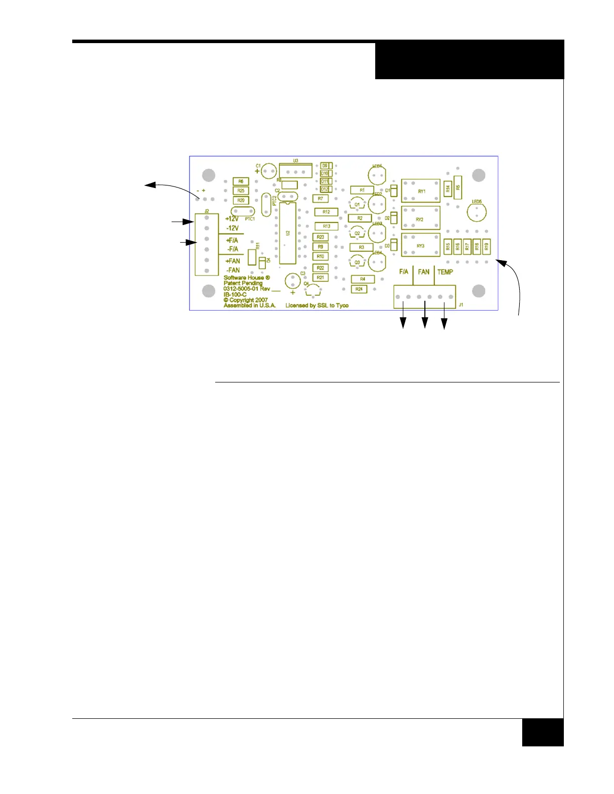
FIGURE 4. Alarm Board Layout
Connect Front Panel Alarms to Inputs
The Fire Alarm, Fan Failure, and Over Temperature alarms can be wired to
ACM inputs and used to create events in the C•CURE system. The alarms are
supervised as NC inputs on the Alarm board.
Steps to monitor the alarms:
1. Select unused inputs on an ACM.
2. Remove the wires that go to the rear connection panel from the selected
input connector.
3. Wire each pair of pins on Alarm Board J1 to the selected input connector.
4. Configure the inputs and events in the C•CURE system.
+12VDC In
Fire Alarm In
Fan Power Out
Supervision Resistors
for Alarm outputs
Alarm Outputs
(from rear panel)
(connect to inputs on ACM, if desired)