Chapter 4: Connecting the Firefighter Gateway to the SolarEdge Installation
Firefighter Gateway Installation Guide MAN-01-00113-1.2
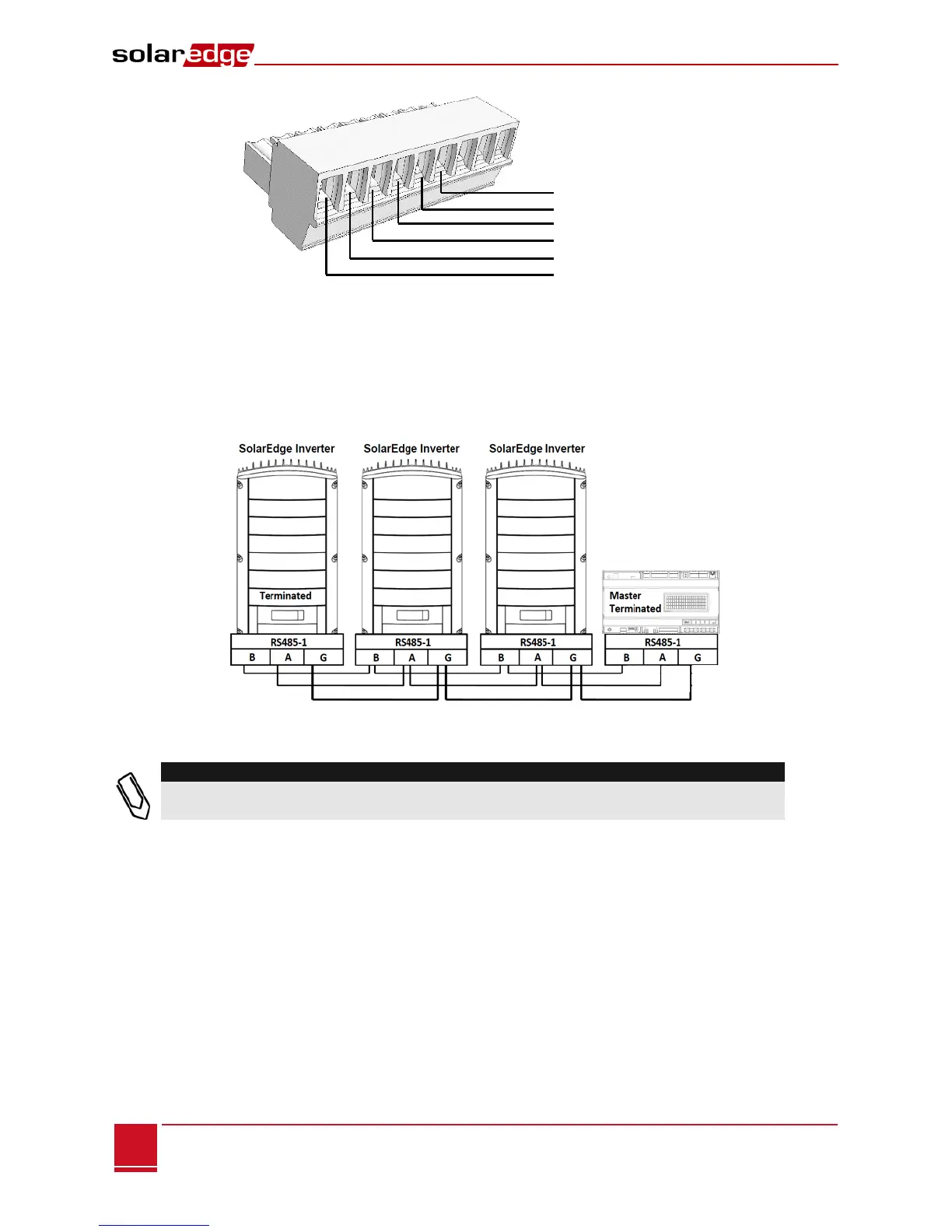
Figure 14: RS485/RS232 Terminal Block
8 Insert the ends of wires into the G, A and B pins shown above. You can use any color wire for each of
the A, B and G connections, as long as the same color wire is used for all A pins, the same color for all
B pins and the same color for all G pins.
9 Connect all B, A and G pins in all inverters/SMI. The following figure illustrates this connection
schema (the illustration applies to both inverters and SMI):
Figure 15: Connecting SolarEdge Devices (Inverters or SMI) in a Chain
Do not cross-connect B, A and G wires.
For inverters - Do not insert wires into RS485-2 pins.