Chapter 4: Connecting the Firefighter Gateway to the SolarEdge Installation
Firefighter Gateway Installation Guide MAN-01-00113-1.2
10 Tighten the terminal block screws.
11 Push the RS485 terminal block firmly all the way into the communication board.
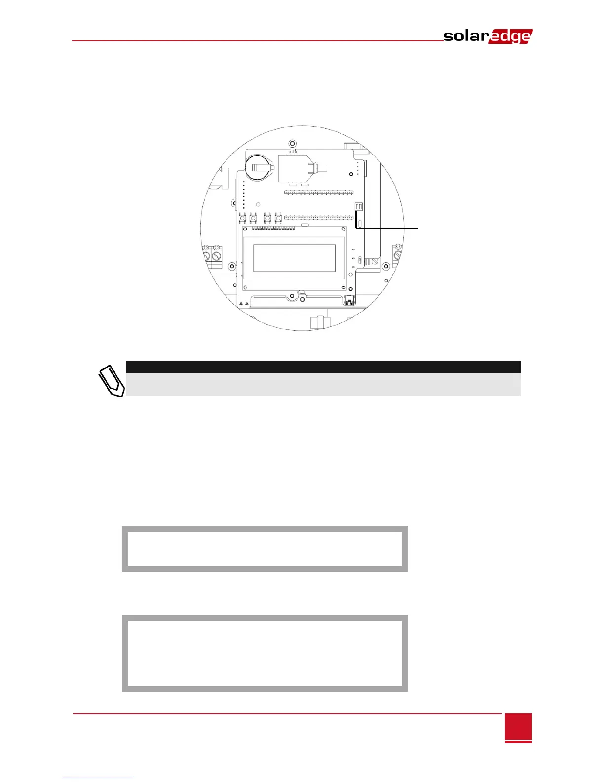
12 Terminate the inverters/SMIs at the two ends of the chain by switching a termination dipswitch
inside the inverter/SMI to ON (move the switch to the top). The switch is located on the
communication board and is marked SW7.
Figure 16: RS485 Termination Switch
Only the first and the last SolarEdge devices in the chain should be terminated. The other
devices in the chain should have the termination switch OFF.
► To configure the RS485 communication bus with SolarEdge inverters/SMI:
By default, all SolarEdge devices are pre-configured as slaves. Slaves can be further configured using the
RS485-x Conf option in the Communication menu.
One device must be set as the master on the RS485 bus. Any one of the SolarEdge devices may be the
master (firefighter gateway, inverter, or SMI). If you connect the installation to the SolarEdge monitoring
portal, the device used to connect to the server must be the master.
The following describes how to configure the master device.
1 Press the Enter button until the following message is displayed:
P l e a s e ente r
P a s s w o r d
* * * * * * * *
The gateway is now in Setup mode and all its LEDs are lit.
2 Use the three-right-most LCD buttons to type in the following password: 12312312. The following
menu is displayed:
L a n g u a g e < e n g >
C o m m u n i c a t i o n
R e m o t e S h u t d o w n
D i s p l a y
M a i n t e n a n c e
I n f o r m a t i o n