Figure 29: RS485 terminal block
5.
Insert the wire ends into the G, A and B pins shown above. Use Four- or six-wire
twisted pair cable for this connection.
You can use any color wire for each of the A, B and G connections, as long as:
The same color wire is used for all A pins the same color for all B pins and the
same color for all G pins
The wire for G is not from the same twisted pair as A or B.
6.
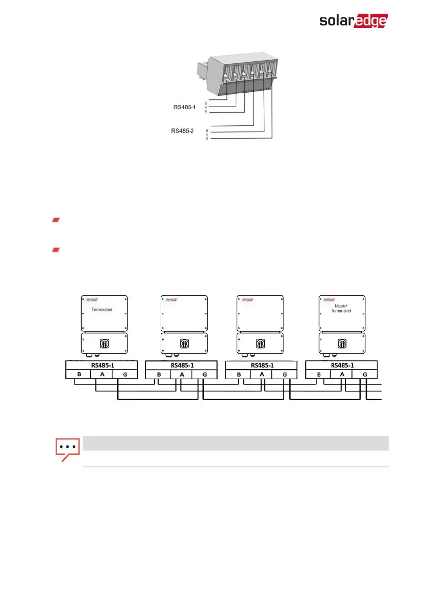
For creating an RS485 bus - connect all B, A and G pins in all inverters. The following
figure shows this connection schema:
Figure 30: Connecting the inverters in a chain
NOTE
Do not cross-connect B, A and G wires.
7. Tighten the terminal block screws.
8. Check that the wires are fully inserted and cannot be pulled out easily.
9.
Push the RS485 terminal block firmly all the way into the connector on the right side
of the communication board.
10.
Terminate the first and last SolarEdge device in the chain by switching a termination
DIP-switch inside the inverter to ON (move the left switch up). The switch is located
Single Phase Inverter with HD-Wave Technology Installation MAN-01-00541-1.3
58 Creating an RS485 Bus Connection