NOTE
If using a cable longer than 10 m/33 ft in areas where there is a
risk of induced voltage surges by lightning, it is recommended
to use external surge protection devices. For details refer to:
https://www.solaredge.com/sites/default/files/overvoltage_
surge_protection_na.pdf.
If grounded metal conduits are used for routing the communication wires, a
lightning protection device is not required.
If not using surge protection, connect the grounding wire to the first inverter
in the RS485 chain; make sure the grounding wire is not in contact with other
wires. Connect the grounding wire to the grounding bus-bar in the Safety
Switch.
The following sections describe how to physically connect the RS485 bus and how to
configure the bus.
To connect the RS485 communication bus:
1. Remove the inverter cover as described in
Removing the Inverter Cover
on page 51.
2. Remove the seal from one of the openings in communication gland and insert the
wire through the opening.
3.
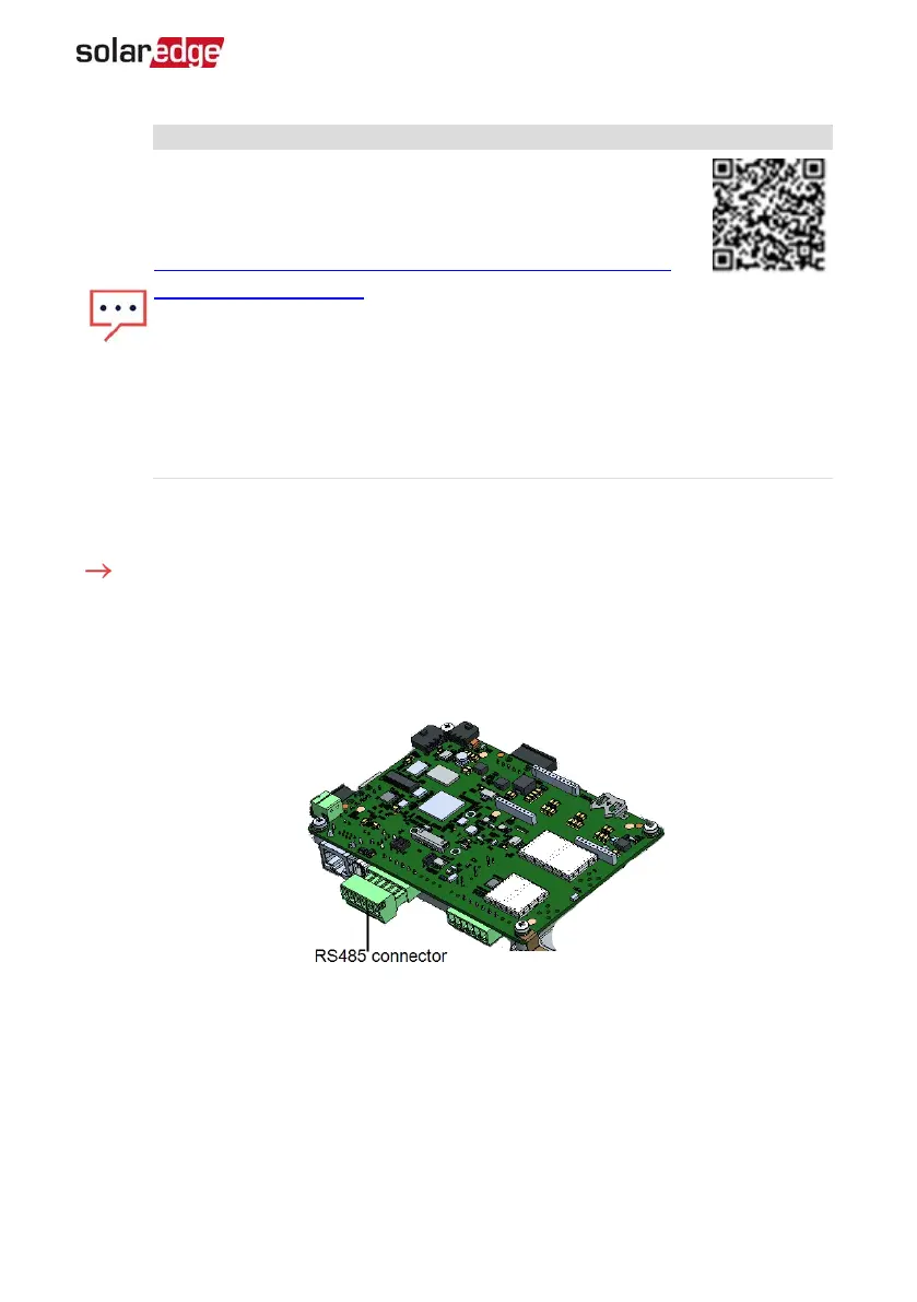
Pull out the RS485 terminal block connector, as shown below.
Figure 28: RS485 terminal block on the communication board
4.
Loosen the screws of pins A(+), B(-), and G on the left of the RS485 terminal block
(RS485-1 ).
Chapter 6: Setting Up Communication to the Monitoring Platform 57
Single Phase Inverter with HD-Wave Technology Installation MAN-01-00541-1.3