To connect the Ethernet cable:
1. Open the communication gland.
CAUTION!
The gland includes a rubber waterproof fitting, which should be used to
ensure proper sealing.
2. Remove the rubber fitting from the gland and insert the CAT5/6 cable through the
gland and through the gland opening in the Connection Unit .
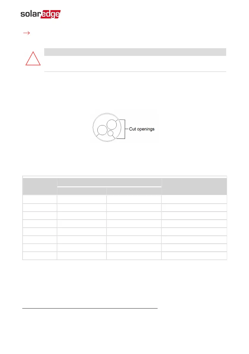
3. Remove the plastic seal from the large opening that has a cut in the rubber fitting.
4.
Push the cable into the cut opening of the rubber fitting.
Figure 33: Communication gland and rubber fitting
CAT5/5E STP cables have eight wires (four twisted pairs), as shown in the diagram
below. Wire colors may differ from one cable to another. You can use either wiring
standard, as long as both sides of the cable have the same pin-out and color-coding.
RJ45 Pin #
Wire Color
(1)
10Base-T Signal
100Base-TX Signal
T568B T568A
1 White/Orange White/Green Transmit+
2 Orange Green Transmit-
3 White/Green White/Orange Receive+
4 Blue Blue Reserved
5 White/Blue White/Blue Reserved
6 Green Orange Received-
7 White/Brown White/Brown Reserved
8 Brown Brown Reserved
(1)
The connection does not support RX/TX polarity change. Supporting crossover Ethernet cables depends on the switch
capabilities.
Chapter 6: Setting Up Communication 67
Three Phase Inverter with Synergy Technology Installation MAN-01-00402-1.2