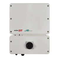
Figure 34: Standard cable wiring
5. Use a pre-crimped cable to connect via the gland to the RJ45 port on the
inverter's communication board or, if using a spool of cable, connect as follows:
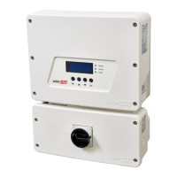
a.
Insert the cable through the gland.
Figure 35: Inserting communication cables
b. Remove the cable’s external insulation using a crimping tool or cable cutter
and expose eight wires.
c. Insert the eight wires into an RJ45 connector, as described
Figure 34
.
d. Use a crimping tool to crimp the connector.
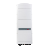
e. Connect the Ethernet connector to the RJ45 port on the communication board
as shown in
Figure 34
.
Figure 36: Connection Unit Communication board
-Three Phase Inverter with Synergy Technology Installation MAN-01-00402-1.2
68 Creating an Ethernet (LAN) Connection