To connect the Ethernet cable:
1. Remove the Smart EV Charger covers as described in
Removing the Smart EV Charger
Covers
on page 24.
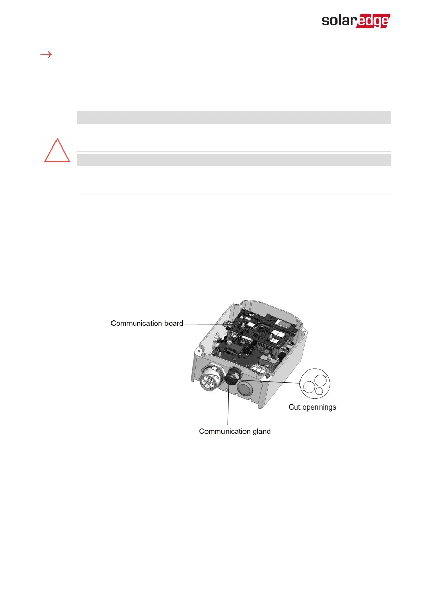
2. Open the communication gland.
CAUTION!
The gland includes a rubber waterproof fitting, which should be used to
ensure proper sealing.
ATTENTION!
Le cote interne du gland contient une rondelle qui doit être utilisée pour une
bonne étancheïté.
3. Remove the plastic seal from one of the large openings.
4. Remove the rubber fitting from the gland and insert the CAT5/6 cable through the
gland and through the gland opening in the Smart EV Charger.
5. Insert the cable through the opening in the Smart EV Charger towards the
communication board.
6.
Push the cable into the cut opening of the rubber fitting (see the following figure).
CAT5/6 standard cables have eight wires (four twisted pairs), as shown in the diagram
below. Wire colors may differ from one cable to another. You can use either wiring
standard, as long as both sides of the cable have the same pin-out and color-coding.
Smart EV Charger Installation MAN-01-00657-1.0
39 Creating an Ethernet (LAN) Connection