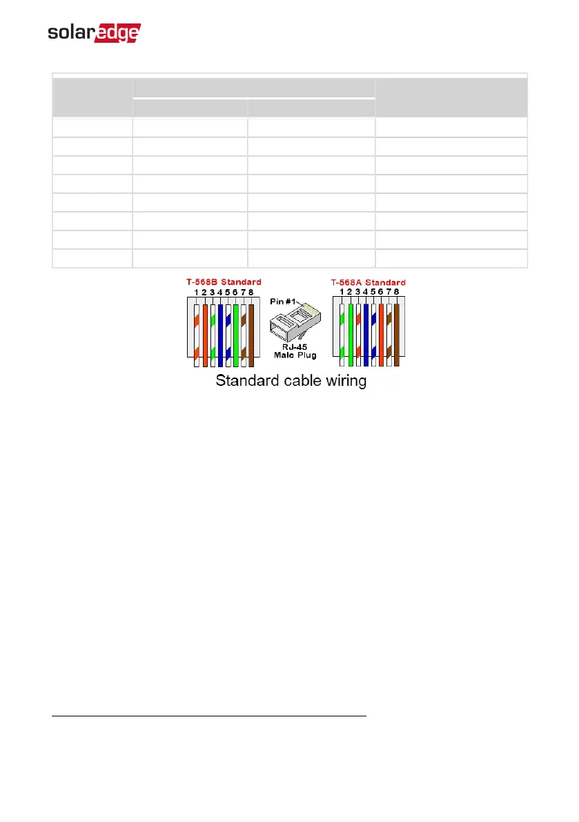
RJ45 Pin #
Wire Color
(1)
10Base-T Signal
100Base-TX Signal
T568B T568A
1 White/Orange White/Green Transmit+
2 Orange Green Transmit-
3 White/Green White/Orange Receive+
4 Blue Blue Reserved
5 White/Blue White/Blue Reserved
6 Green Orange Received-
7 White/Brown White/Brown Reserved
8 Brown Brown Reserved
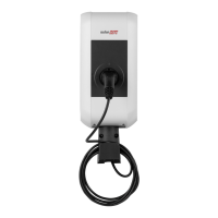
7. Use a pre-crimped cable to connect via gland #1 to the RJ45 plug on the Smart EV
Charger's communication board or, if using a spool of cable, connect as follows:
a. Insert the cable through the gland.
b. Remove the cable’s external insulation using a crimping tool or cable cutter and
expose eight wires.
c. Insert the eight wires into an RJ45 connector, as described in
d. Use a crimping tool to crimp the connector.
e. Connect the Ethernet connector to the RJ45 port on the communication board
(see the following figure).
(1)
The Smart EV Charger connection does not support RX/TX polarity change. Supporting crossover
Ethernet cables depends on the switch capabilities.
Chapter 6: Professional Installer - Setting Up Communication 40
Smart EV Charger Installation MAN-01-00657-1.0