8 Options
8.1 Accessory components
Below you will nd a list of other available accessory components.
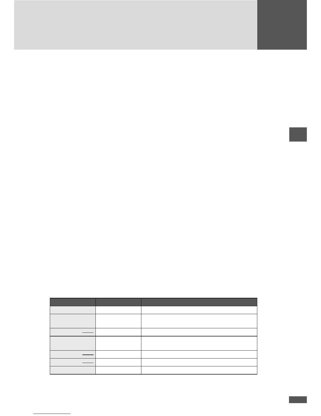
n MaxMeteo
Unit recording irradiation data and cell temperature of PV modules
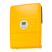
n MaxCount
Unit recording meter gures with S0 interface
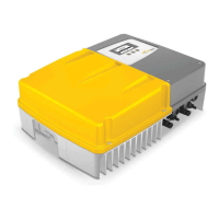
n MaxDisplay
Interface for a large display to visualise PV plant data
9 Operating status
9.1 Status messages and status LED
The status message in the graphics display describes the current operating status of the
inverter. Each inverter status message belongs to one of the ve possible operating sta-
tuses. The status LED always displays one of these operating statuses through a variety
of colours. In addition to the status messages, the inverter can also display warnings.
Warnings result from device errors or external failures which, however, do not affect the
mains operation of the inverter. Losses of yield are possible, however.
Warnings have no relation to the operating status and are displayed on the graphics dis-
play alternately with the current status message.
The status messages of the “Failure”, “Error”, and “Blocked” operating statuses, as well
as the warnings, usually require certain measures to be taken, see 10 “Troubleshooting”;
page 100.
LED status Operating status Description
Off - Inverter is switched off > grid disconnection
Flashing green
– – –
Booting Inverter starts > grid disconnection
Green
Mains operation Grid feed-in (normal operation)
Flashing
orange – – –
- Warning > no grid disconnection
Orange
Failure External failure > grid disconnection
Red
Error Internal device error > grid disconnection
Flashing red – – – Blocked Inverter is blocked > grid disconnection