9
en
Additionally, in the SP Series inverters integrate the following protection
devices:
● Internal overvoltage
● DC insulation monitoring
● Ground fault protection
● Grid monitoring
● Current leakage protection
● DC current monitoring protection
● DC disconnector integrated
● Reverse DC polarity protection
3�3 Front panel
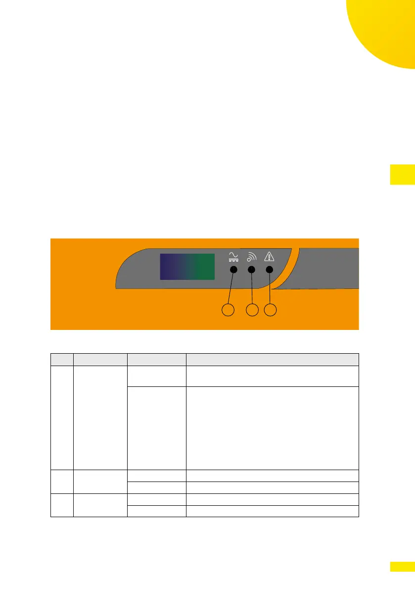
3�3�1 LED indicators
1 2 3
Fig. 2: Status indicators on the front panel of the SP inverters
LED Description State Description
1
Grid indicator Blink Grid voltage absent or out of range. It is not pos-
sible to connect the inverter to the grid.
ON, with blinks
every 30 sec
Normal operation.
The LED is normally ON, but every 30 sec it blinks
according to the current power level vs. the nom-
inal power.
1 blink = <20 % of nominal power
2 blinks = 20 % to 40 %
3 blinks = 40 % to 60 %
4 blinks = 60 % to 80 %
5 blinks = 80 % to 100 %
2
Communica-
tion indicator
Blink Data communication underway
OFF No communication
3
Warning
indicator
ON / blink A warning occurred. Refer to the error table.
OFF No warning