24
25
4. Installation
4. Installation
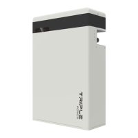
4.5.3 Connecting CAN Communication Cable
It is required for the BMS to communicate with the inverter for proper operation.
2. Insert the other end of the CAN communication
cable to the CAN connector ( )on the rst battey II
which is marked in red.
Assemble the cable gland and tighten the cable
cap.
1. Insert one end of the CAN communication
cable (C) directly to the BMS port of the inverter.
BAT- BAT+
CAN
Thewiringorderofthecommunicationcableisasfollow:
1 2
3
4
5
6 7 8
Sequence
1 2 3 4 5 6 7 8
CAN
/
GND
/
CAN_H
CAN_L
/
A1
B1
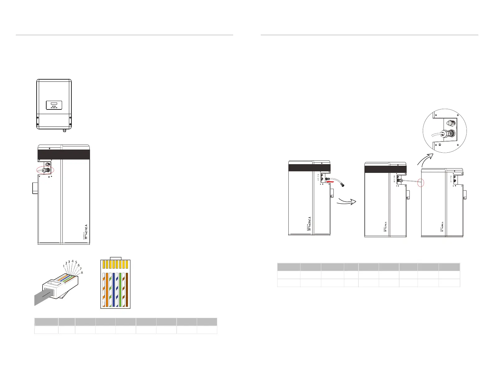
4.5.4 Connecting RS485 Communication Cable
For T-BAT H 5.8:
There's no need to use RS485 communicaton cable.
For T-BAT H 5.8 + 1~3 battery packs:
Connect RS485 II ( for T-BAT H 5.8 or for HV11550) of the rst battey packVII VIII’
(as shown on the right) to RS485 I on the next battery pack(as shown on the left).
Assemble the cable gland and tighten the cable cap.
Sequence 1 2
3
4 5
6
7 8
RS485I
RS485II
VCC_485
VCC_485
GND_485
GND_485
B2
B2
N-
N-
P+
P+
A2
A2
VCC_485_2
VCC_485_2
GND_485
GND_485
The wiring order of the communication cable is as follow:
-
YPLUG
RS485 II
-
YPLUG
RS485 II
-
YPLUG
RS485 II
+
XPLUG
RS485 I
1) Orange stripes on white
2) Orange
3) Green stripes on white
4) Blue
5) Blue stripes on white
6) Green
7) Brown stripes on white
8) Brown
 Loading...