Electrical Connection
Electrical Connection
62
63
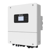
1 2
3
4
5
6 7 8
1) White with orange stripes
2) Orange
3) White with green stripes
4) Blue
5) White with blue stripes
6) Green
7) White with brown stripes
8) Brown
Multifunction terminal
crimping tool (RJ45)
Step 3. Insert the prepared communication cables into the RJ45 terminals
in sequence, and then use network cable crimping pliers to
press them tightly.
METER/CT pin is defined as follow:
1 2
3
4
5
6 7 8
Ø METER/CT communication cable
1
8
1
2 3 4 5 6 7 8
485A 485B X
CT1-2CT1-1
CT2-2
CT2-1
X
A
B
Notice!
Only one of the Meter and CT connections can be selected.
Meter cable goes to pin terminal 4 and 5; CT cable goes to pin
terminal 1 and 8; CT2 cable goes to pin terminal 3 and 6.
1) Users can customize the length of the CT communication cable. The
accessory package provides 1*RJ45 and 1*waterproof connector with
RJ45 terminals.
When the CT cable is completed, connect the A terminal to the
"CT/METER" port of the inverter and tighten the waterproof screw, and
connect the B terminal to the RJ45 coupler.

 Loading...