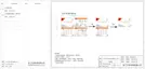
h) Remove the blue protective cover of the PV +&- interface at the bottom of
the inverter, and insert the completed PV terminals according to the positive
and negative correspondence.
NOTE!
Keep the DC switch of the inverter OFF during connection.
26
27
Grid Connection
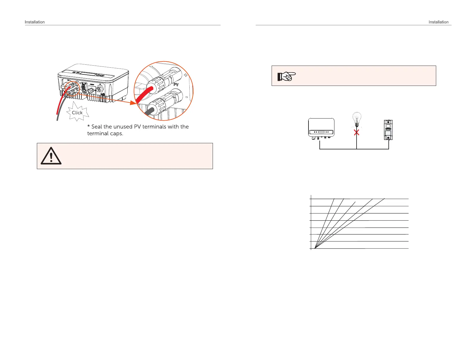
Incorrect Connection between Load and Inverter
1.4 0%
1.2 0%
1.0 0%
0.8 0%
0.6 0%
0.4 0%
0.2 0%
0.0 0%
loss
0m 10m 20m 30m 40m 50m 60m 70m 80m 90m 100m 110m
2.0 mm²
4.0 mm²
6.0 mm²
8.0 mm²
10.0 mm²
NOTE!
The inverter is designed for single phase grid. Voltage range is 220/
230/ 240 V, frequency is 50/ 60 Hz. Other technical requests should
comply with the requirement of the local public grid.
Inverters should not be used in multiple phase combinations.
Micro-breaker should be installed between inverter and grid, any loads
should not be connected with inverter directly.
Ø
Impedance of the Inverter AC connecting dot should be less than 2 Ω. To
ensure reliable anti-islanding function, PV cable should be used to ensure
wire loss < 1% than normal power. Moreover, length between AC side and
grid connecting dot should be less than 150 m. The following chart is the
cable length, section area and wire loss.
This product has a professional IP67 AC waterproof connector (after connection).
You have to wire AC by yourself. Please see the figure above.

 Loading...