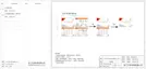
Component 1 Component 2 Component 3
d) The AC connector provided in the packing list includes 2 parts (A and B).
A
B
- Separate A into 2 components.
- Then the AC connector is finally classified into 3 components for
use (as shown below).
Connection Steps
a) Check the grid voltage and compare with the permissive voltage range
(refer to technical data).
b) Disconnect the circuit-breaker from all the phases and secure against
re-connection.
c) Strip the wires:
- Strip L and N wires to 52.5mm and the PE wire to 55mm.
- Use the crimping pliers to strip 6mm of insulation from all wire ends as
below.
28
29
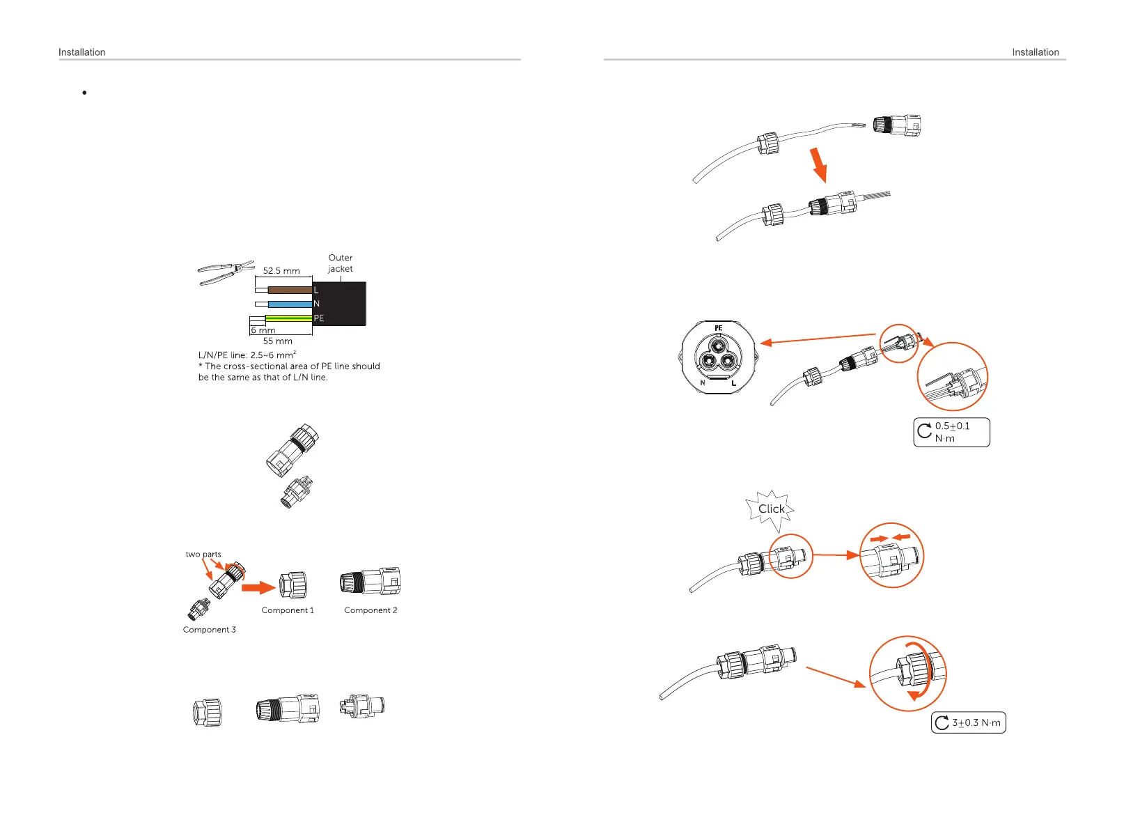
e) Slide the component 1 and component 2 onto the cable.
g) component 2.Insert component 3 into
h) Screw down the component 1 tightly. (torque: 3±0.3N·m)
f) Insert the stripped end of each three wires into the appropriate hole in
the component 3, and then tight each screw (to tight each wire in place).
(Allen wrench. Torque: 0.5±0.1N·m)

 Loading...