59 • Installation
________________________________________________________________________________________________
Continuous mode (factory default) – Fan operates as long as the control supply is connected to terminals 1-
3. Leave the internal jumper connected to the left terminal of JI (marked A in the drawing).
External control mode – Fan operates when the control supply is connected to terminal 2. Connect the
internal jumper to the middle terminal of JI terminal (marked B in the drawing). For use without bypass,
connect the fans before giving the start command and disconnect at least 5 minutes after giving the stop or
soft stop command.
Automatic mode – Whenever the start or stop signals is given the fan operates for approximately 5 minutes.
Connect the internal jumper to the right terminal of JI (marked C in the drawing).
WARNING!
Automatic mode may be used only if bypass contactor is directly controlled by
the RVS-DN’s END OF ACCELERATION contact.
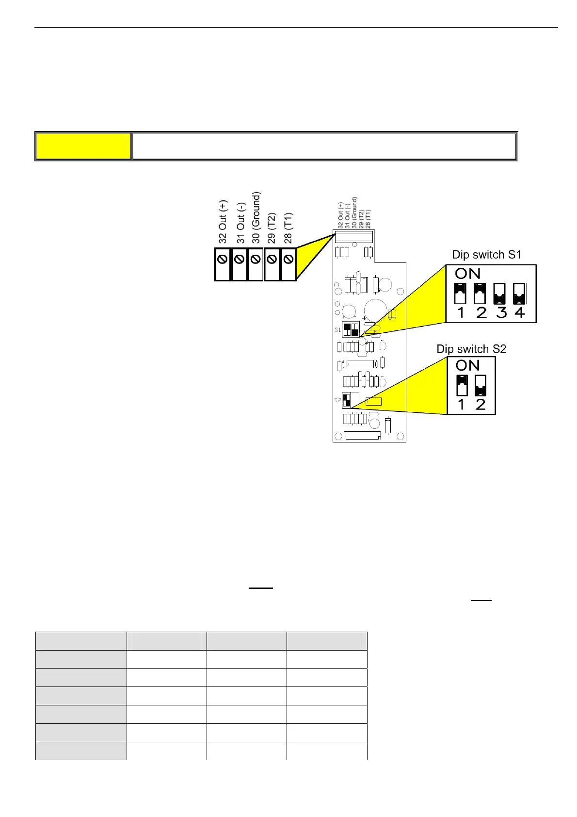
6.7 Analog I/O (Option 5) (Terminals T1, T2, Gnd, Out (-), Out (+))
The analog
option incorporates
two functions:
• Thermistor input
• Analog output
Analog P.C.B. layout
Thermistor Input (Terminals T1, T2)
Programmable as PTC or NTC type thermistor. Trip value is adjustable between 1-10K, preset delay of 2 sec.
For thermistor input programming refer to section
7.7.7 on page 81.
Ground Terminal (terminal Gnd)
Connect the thermistor and/or the analog output shield to this ground terminal.
Analog Output (Terminals Out (+), Out (-))
Dip switches allow selection between: 0-10VDC, 0-20mA, 4-20mA
The analog value is related to I, 0….200% of FLA
(not programmable).
In RVS-DN 1000V and RVS-DN 1200V models the analog value is related to I, 0….200% of FLC
. In RVS-DN
1000V and RVS-DN 1200V models inverse programming is optional as well (refer to section
7.7.8 on page
83).
Switch No. 4-20 mA* 0-20 mA 0-10VDC
Switch # 1 On On Off
Switch # 2 On On Off
Switch # 3 Off Off On
Switch # 4 Off Off On
Switch # 1 On Off Off
Switch # 1 Not used Not used Not used
* Factory default setting