29 • Recommended Wiring diagrams
________________________________________________________________________________________________
4.18 Short Circuit Protection
For “type 2 coordination
”, use fuses for semiconductor protection to protect the RVS-DN from a short circuit.
Fuses for semiconductor protection give excellent results because they have low I²t values and high
interruption ratings.
Recommended fuse selection procedure:
(1) Fuse rated voltage
: Choose minimum fuse rated voltage which is above the rated voltage of the
mains.
(2) Fuse rated current:
Select a fuse which is able to carry 8 times the rated RVS-DN current for 30
seconds (this is double the maximum RVS-DN current for the maximum acceleration time).
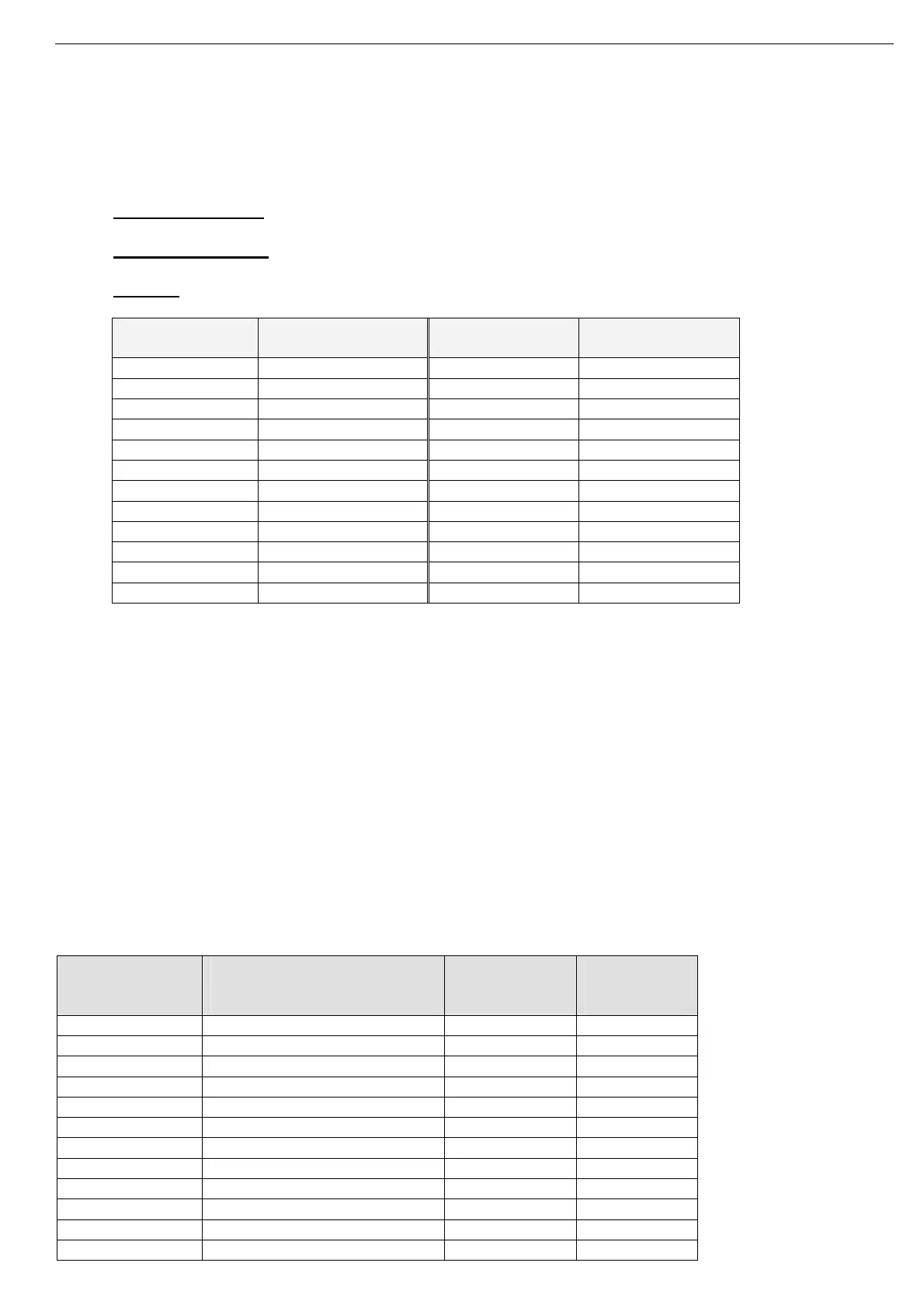
(3) Fuse I²t:
Verify that the I²t value of the fuse is less than or equal to the I²t value of the thyristor in the
RVS-DN as shown in the table below.
RVS-DN Model Max. Thyristor I
2
t
[A2Sec]
RVS-DN Model Max. Thyristor I
2
t
[A2Sec]
8 400 390 700,000
17 5,000 460 800,000
31 10,000 580 1,200,000
44 12,000 820 2,000,000
58 15,000 950 4,500,000
72 18,000 1100 4,500,000
85 50,000 1400 6,500,000
105 60,000 1800 12,500,000
145 100,000 2150 16,500,000
170 140,000 2400 26,000,000
210 200,000 2700 26,000,000
310 600,000 3000 Consult factory
4.19 Transient Protection
Line transie
nt voltages can cause a malfunction of the RVS-DN and damage to the thyristors. All RVS-DNs
incorporate Metal Oxide Varistors (MOV) to protect from normal line voltage spikes.
When higher transients are expected, additional external protection should be used (consult factory).
4.20 UL, cUL Installation Instructions
1.
Input power and output motor field wiring shall be copper conductors, rated 75°C.
2. Use UL listed closed-loop connectors sized for the selected wire gauge. Install connectors using the
correct crimp tool recommended by the connector manufacturer. Applies only to units bus bars.
3. Table showing corresponding wire size, terminal screw, closed-loop connector size. Torque ratings for
attachment of connector to bus bar (see table).
4. Branch circuit protection, shall be provided per the NEC.
For units with UL cUL, see ordering information.
Cables, Terminal Screws and Torque Recommendations
Max. Motor FLA
[A]
Min. Dimensions for
Copper Cables
[mm
2
]
Terminal
Screw
Mechanical
Torque
[Nm]
8 4 x 1.5 N2XY M5 3
17 4 x 2.5 N2XY M5 3
31 4 x 4 N2XY M5 3
44 4 x 10 N2XY M6 4.5
58 4 x 16 N2XY M6 4.5
72 4 x 16 N2XY M6 4.5
85 4 x 25 N2XY M8 15
105 4 x 35 N2XY M8 15
145 3 x 50 + 25 N2XY M8 15
170 3 x 70 + 35 N2XY M10 30
210 3 x 95 + 50 N2XY M10 30
310 3 x 150 + 70 N2XY M12 60