BiG SiX User Guide
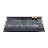
Console Overview
16
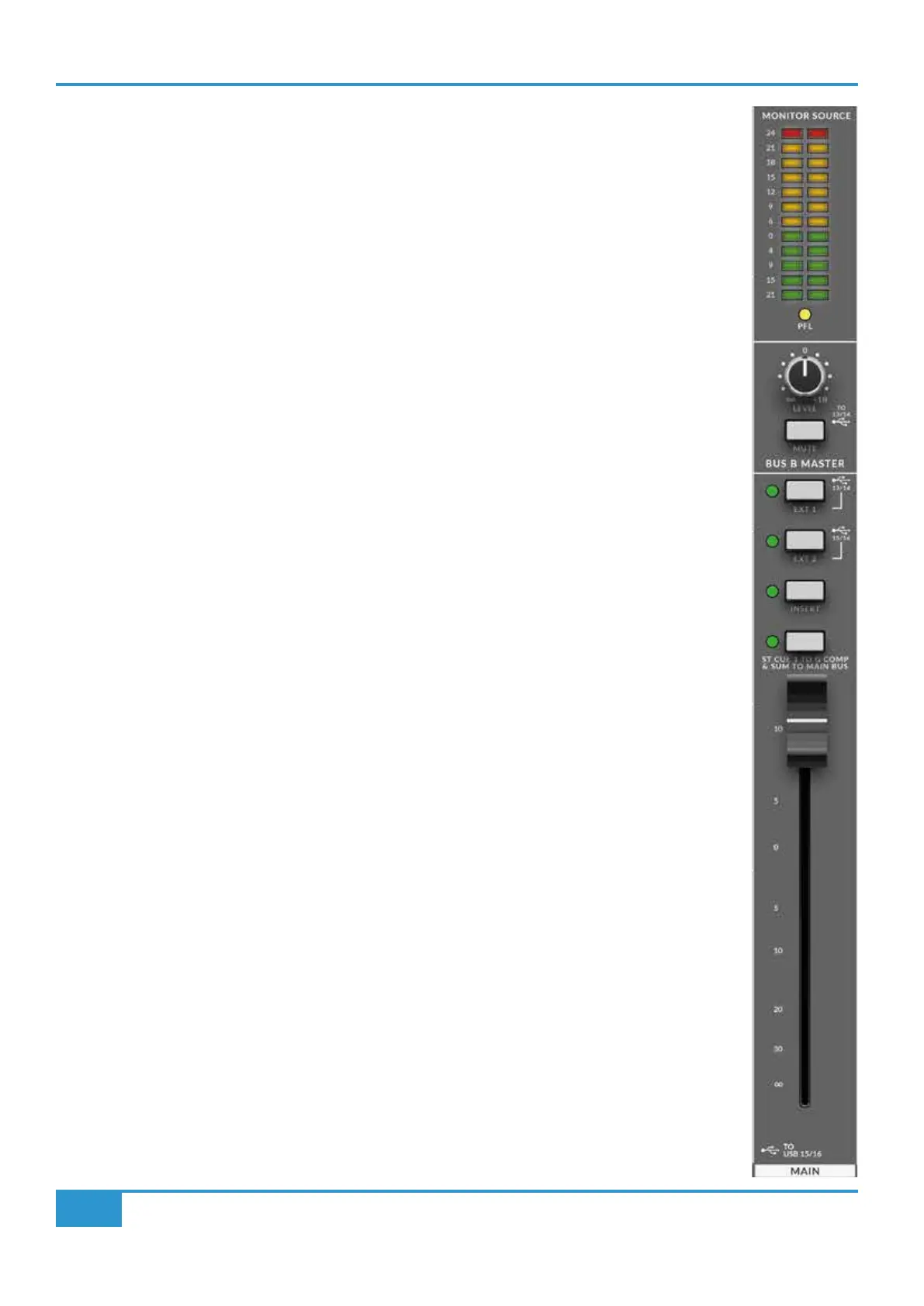
Main Meter
The twelve Segment LED ‘main’ meter in BiG SiX follows the Monitor Source selector to provide a more versatile
output metering solution. The fast response peak meter has specic segments for +24 dBu and +18 dBu as
with the channel meters, it also has a +15 dBu segment for other standards as well as 0 dBu. The meter has a
fast peak response (rise time to 60% Full Scale Deection approx 1 ms @ 1 kHz) and a slower release to meter
peaks while still showing useful signal levels.
Bus B Master
The secondary BUS B in BiG SiX provides an alternate routing for the channel signal outputs when the channel
MUTE keys are pressed. At the rear of the console there are a pair of 1/4" TRS output jacks for Bus B. The LEVEL
control provides a master output level and the MUTE switch mutes the output signal.
The Monitor Source section has a BUS B switch to allow the monitoring of signals on the BUS B output. BUS B
is also routed to via a pair of A/Ds to the USB channel 13 & 14 Sends.
Main Bus
The Main Stereo Bus on BiG SiX connects to dedicated MAIN 1/4" TRS output jacks on the rear connector panel.
These are balanced TRS connectors. Additionally, the Main Bus is connected via a pair of A/Ds to the USB
channel 15 & 16 Sends.
The high quality 100 mm Main Bus stereo fader controls the Main Bus level to the Main outputs and has gain
up to +10 dB. As with the channel faders, the fader law is designed to provide more resolution around the 0 dB
point, allowing subtle level changes from modest fader movements.
External to Main Bus Summing
Above the Main Fader are switches for the Main Bus Insert (See below), EXT 1 and EXT 2. These last three
switches sum these signals onto the Main bus. This provides the ability to sum four additional signals into the
Main bus. An example of how this can be used is to add additional analogue summing from DAW outputs, or to
return effects signals into the main mix.
Main Bus Insert
In the Main Output signal ow is a fully balanced stereo insert. In common with larger SSL consoles, the Insert
Send is always active, while the Insert Return switches into the signal path when selected.
The primary use for this is to insert external processing into the Main Bus signal path. For example to insert an
analogue colouration processor, such as SSL’s Fusion. As the Insert Send is at unity gain, it also provides a
useful pre-processing and pre-fader Main Bus split output.
The switched Insert Return also provides a direct, pre-fader input into BiG SiX's Bus Compressor circuit so that
this circuit can be used outside of the normal BiG SiX signal ow.
The Main Bus stereo insert send and return are connected with 1/4" TRS jacks on the rear panel.