012
MIG 250GS Operating manual
2.4 Fundamentals of MIG, FCAW and MCAW
Welding Technique
Successful welding depends on the following factors:
1 Selection of correct consumables
2 Selection of the correct power source
3 Selection of the correct polarity on the power source
4 Selection of the correct shielding gas
5 Selection of the correct application techniques
a Correct angle of electrode to work
b Correct electrical stickout
c Correct travel speed
6 Selection of the welding preparation
Selection of Correct Consumable
Chemical composition
As a general rule the selection of a wire is straightforward, in that
it is only a matter of selecting an electrode of similar composition
to the parent material. It will be found, however, that there are
certain applications that electrodes will be selected on the basis
of its mechanical properties or level of residual hydrogen in the
weldmetal. Solid MIG wires are all considered to be of the 'low
Hydrogen type' consumables.
The following table gives a general overview of the selection of
some of the SolidARC range of MIG wires for the most common
materials.
Common Materials Welded with SolidARC MIG Wire
Material MIG Wire
AS2074 C1,C2,C3, C4-1,C4-
2,C5,C6
Mild Steel MIG Wire
BS3100 AW1,A2,A3 Mild Steel MIG Wire
BS1504-430,480,540 Mild Steel MIG Wire
ASTM A36,A106,EN8,8A Mild Steel MIG Wire
Stainless Steel
Grade 304 Stainless Steel 308LSi
Grade 309 Stainless Steel 309LSi
Grade 316 Stainless Steel 316LSi
Physical condition
Surface condition
The welding wire must be free from any surface contamination
including mechanical damage such as scratch marks.
A simple test for checking the surface condition is to run the wire
through a cloth that has been dampened with acetone for 20 secs.
If a black residue is found on the cloth the surface of the wire is not
properly cleaned.
Cast and Helix
The cast and helix of the wire has a major influence on the
feedability of MIG wire.
If the cast is too large the wire will move in an upward direction
from the tip when welding and if too small the wire will dip down
from the tip. The result of this is excessive tip wear and increased
wear in the liners.
If the helix is too large the wire will leave the tip with a corkscrew
effect.
Typical Metal Transfer Mode
Process
Dip
Transfer
Globular
Transfer
Spray Transfer
Metal Inert Gas
(MIG)
✓ ✕ ✓
Flux Cored
(Gas Shielded)
✓ ✓
✓*
Flux Cored
(Self Shielded)
✓✓ ✓ ✓✕
Metal Cored
✓✓
✕
✓✓
* Not True Spray
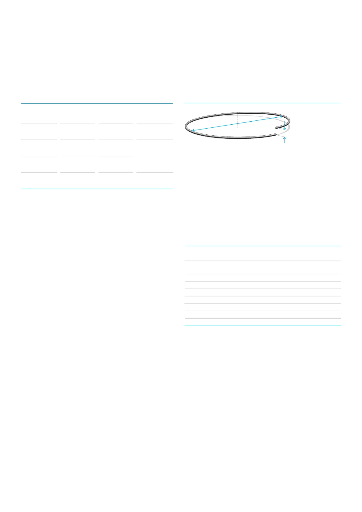
Cast
Helix
Cast – Diameter of the circle
Helix – Vertical height
Cast and Helix