027
MIG 250GS Operating manual
$036 :)6
6PRRWKDUF
$GYDQFH$GYDQFH
,,
&
7
7
92/7$*(,1'8&7$1&(
&5$7(5
$5&&855(17
9
$
PPLQ
9
7.1 MIG Welding Set-up
1 Ensure the machine is correctly plugged into the main circuit
2 Proper PPE must be worn
3 Ensure workplace safety such as fume extraction is in place
4 Switch machine on using On/Off switch at the back of the
machine
5 Open gas cylinder and set gas flow rate
6 Set voltage and wire feed speed (the tables included in this
manual can be used as a guideline for voltage and wire speed
selection)
7 Voltage is set by adjusting voltage knob (1) on power source
8 Wire feed speed can be set independently by adjusting the wire
feed speed/Arc current knob (2)
9 Inductance can be changed by adjusting the inductance knob (3)
on the power source
10 Welding wire can be fed through the torch by selecting “Wire
Inch” button located inside the power source above the wire
feeder.
11 For certain types of self shielded flux cored wires it is required to
change the polarity. This can be achieved by switching the work
return lead and clamp from the negative dinse connector (5)
to the positive dinse connector (4). The pigtail needs to then
change from the positive dinse connector (4) to the negative
dinse connector (5).
7.2 MMA Welding Set-up
1 Ensure the machine is correctly plugged into the main circuit
2 Proper PPE must be worn
3 Ensure workplace safety such as fume extraction is in place
4 Switch machine on using On/Off switch at the back of the
machine
5 Select process by depressing the process selection switch (7)
to MMA
6 Fit work return lead to negative dinse*
7 Fit electrode holder to positive dinse connector*
8 Select Amperage by turning by wire feed speed/Arc current
knob (2)
*
DCEP Connection. For DCEN when recommended by the
consumable supplier, reverse the terminals as stated in
points 6 & 7.
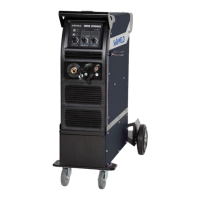
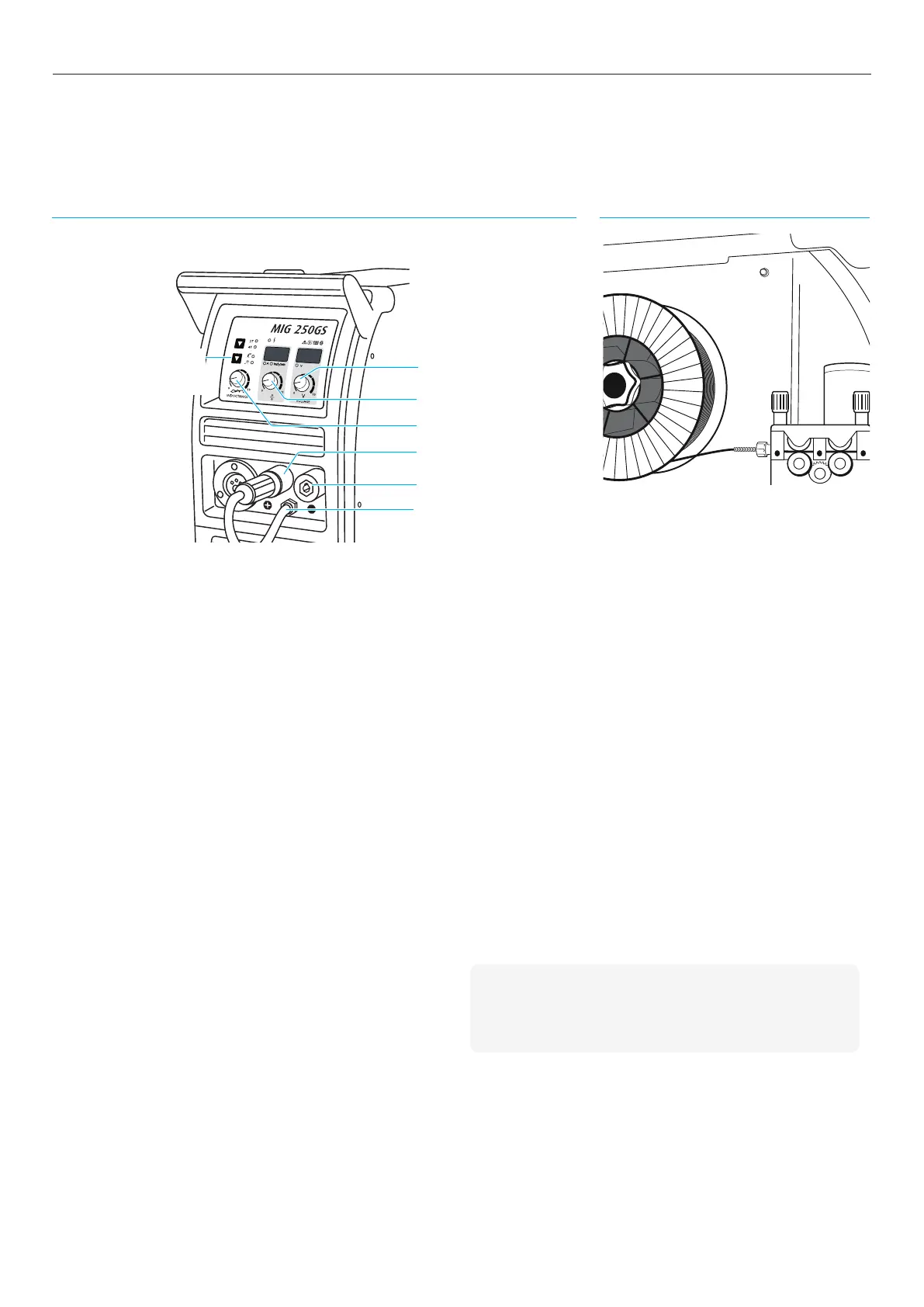
7.0 Operation Set-up
Front of MIG 250GS Inside of MIG 250GS
2 Wire feed speed and Arc current
5 Negative dinse connector
1 Voltage
4 Positive dinse connector
7 Process selection switch
(MMA, MIG)
3 Inductance
6 Pigtail
Wire Inch