20
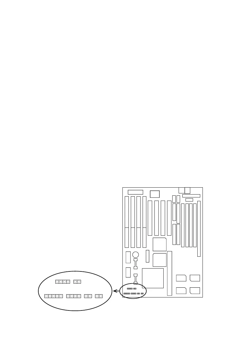
J3: Reset Switch
The system board has a 2-pin connector for rebooting your
computer without having to turn off your power switch.
This prolongs the life of the systemÕs power supply.
J2: Keylock Switch
The keylock switch is a 5-pin connector for locking the
keyboard for security purposes. (See the following drawing
for jumper position, and pin1~3 is connected to power LED
and pin 4~5 is connected to keylock switch.)
J1: Speaker Connector
The speaker connector is a 4-pin connector for connecting
the system and the speaker. (See the following drawing for
jumper position.)
J4: IDE LED Activity Light
This connector connects to the hard disk activity indicator
light on the case.
+
–
Keylock J4 SM1
J5
Reset
SPK
JP9
T/LED
HD/LED J6J2
J1
1