28
A11 A13 A21 A22 A23 A24 A31 A32
34786 34786 34786 34786 34786 34786 34787 34787
A33 A34 A41 A42 A43 A44 A51 A52
34787 34787 34788 34788 34788 34788 34788 34788
3°
Edition: 2021-04 Original document - Mi-205 EN
Use a puller to disassemble the actuator from the butterfly valve. This prevents
damage to the seat and the butterfly of the valve.
1. Undo the clamping ring bolts (
➔ Fig.5-8/4).
2. Remove the accessory parts such as positioners and end position limit
switches.
3. Remove the screws (
➔ Fig.5-8/3), to remove the driver (➔ Fig.5-8/2).
4. Remove the bracket (
➔ Fig.5-8/6) from the butterfly valve by removing the
bolts (
➔ Fig.5-8/5).
5. Press the actuator off the valve with the puller (
➔ Fig.5-8/1). Turn the puller in
until the actuator can be removed from the valve shaft.
6. Lift the actuator off and turn the puller out again.
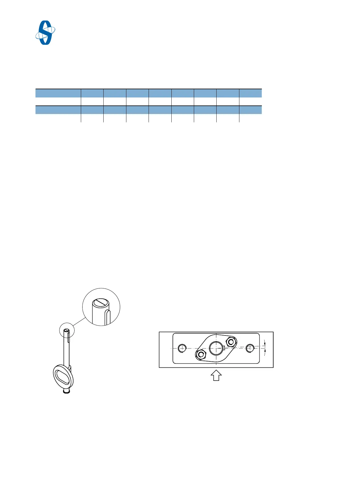
5.5 Positioning of the shaft with disassembled actuator
A line at the end of the shaft, marks the position of the butterfly in the butterfly
valve. The line must be parallel to the butterfly valve body, when the valve is
closed and the key in the flow direction points to the right (
➔ Fig.5-9).
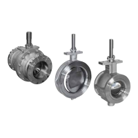
Fig.5-9 Marking (at the end of the shaft) Fig.5-10 Slot angle
To ensure that the valve in combination with an actuator without overtravel
achieves the closing position (
➔ Fig.5-10) the slot of the key is turned out of the
centre line aprox. 3°.
The tightness of the butterfly valve depends on the closing torque.
Pullers
Actuator size
Article no.
Actuator size
Article no.