— 17 —
CPD-E530
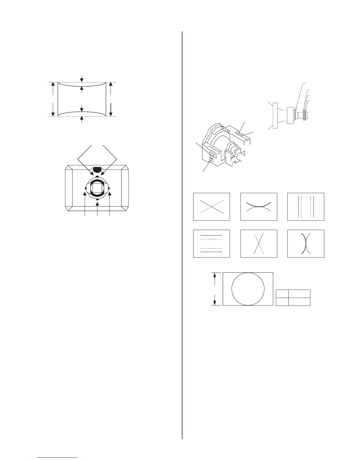
16. Adjust the vertical angle of the DY to make the top and bottom pins
equal (a = b). The horizontal angle is not changed (straight). Settle
DY upright without leaning, and insert wedges rmly so that the DY
does not move.
a
b
c d
<How to place wedge>
Green plain crosshatch pattern
a and b should be equal.
c and d should be equal.
Plaster RTV to both sides for the upper wedge.
Make sure that they settle inside DY.
Plaster RTV to one side for other wedges.
17. Adjust the top and bottom pins correction VR.
18. Adjust the horizontal trapezoid distortion by DY horizontal trapezoid
correction VR.
19. Check the landing at each corner. If the landing is not set to
specication, adjust the landing of the 4 corners with LCC_NS,
LSS_LT, LCC_LB, LCC_RT, and LCC_RB. The limitations of
registers are shown below:
LCC_NS: 128 ± 15
LCC_LT, LCC_LB, LCC_RT, and LCC_RB: 128 ± 40
20. Remove the sensor and wobbling coil.
21. Switch signals to R, G, B, and then check that the pure colors have
good color purity.
22. Fix purity magnets with white paint.
3-3. CONVERGENCE ROUGH
ADJUSTMENT
1. Display the white crosshatch pattern.
2. Pile the convex parts of the 6-pole magnet for convergence
together.
3. Roughly adjust H.CONV and V.CONV with the 4-pole magnet.
XBVXCV
B
R
B
R
R
B
B
R
R
BB R
TLV
TLH
YBHYCH
R B
R B
Convergence Specification
B
A
A
0.20 mm
B
0.24 mm
V
3-4. WHITE BALANCE ADJUSTMENT
SPECIFICATION
1. 9300 K
x = 0.283 ± 0.005
y = 0.298 ± 0.005
(All White)
2. 6500 K
x = 0.313 ± 0.005
y = 0.329 ± 0.005
(All White)
3. 5000 K
x = 0.346 ± 0.005
y = 0.359 ± 0.005
(All White)