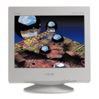
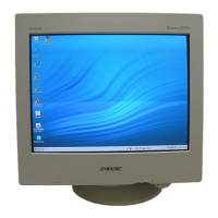
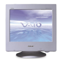
Do you have a question about the Sony CPD-E530 and is the answer not in the manual?
Details the aperture grill pitch and screen size of the picture tube.
Specifies the maximum and recommended horizontal and vertical resolution.
Lists the horizontal and vertical deflection frequency ranges.
Information on DDC2B/DDC2Bi and GTF compliance for Plug and Play.
Explains how to interpret LED flashing patterns for fault diagnosis.
Highlights critical components requiring specific part replacements for safety.
Provides step-by-step instructions for removing the monitor cabinet.
Details the procedure for safely removing the picture tube.
Procedure for checking and adjusting the high voltage regulator circuit.
Initial adjustment for picture landing and color purity.
Covers the rough adjustment process for color convergence.
Instructions for adjusting the focus for optimal picture clarity.
Diagram illustrating the physical location of major circuit boards.
Detailed schematic diagrams for various electronic boards.
Illustrations and identification of semiconductor components used.
Exploded view of the chassis assembly with associated part numbers.
Exploded view detailing the picture tube assembly.
Electrical parts list for the H1 board.
Electrical parts list for the A1 board.
Guide to connect the monitor to a computer via HD15 connector.
Instructions on how to switch between connected computers.
Steps to diagnose and resolve issues when there is no picture displayed.
How to use the monitor's self-diagnosis feature for troubleshooting.
Safety advice regarding power cord usage and connections.
Guidelines for proper monitor installation environment.
Table listing supported resolutions, frequencies, and modes.
Instructions for printing large schematic diagrams.
Steps to use the PDF's search function to find components.
| Screen Size | 21 inches |
|---|---|
| Max Resolution | 1600 x 1200 |
| Refresh Rate | 85 Hz |
| Dot Pitch | 0.24 mm |
| Brightness | 200 cd/m² |
| Contrast Ratio | 500:1 |
| Viewable Image Size | 19.8 inches |
| Input Video Signal | Analog RGB |
| Aspect Ratio | 4:3 |
| Display Type | CRT |
| Input Connectors | VGA, BNC |
| Power Consumption | 120 W |


 Loading...