Components not identied by a part number or
description are not stocked because they are seldom
required for routine service.
NOTE: The components identied by shading and
!
mark are critical for safety.
Replace only with part number specied.
NOTE: Les composants identies per un trame et une marque
!
sont critiques pour
la securite. Ne les remplacer que par une piece portant le numero specie.
The component parts of an assembly are indicated by
the reference numbers in the far right column of the parts
list and within the dotted lines of the diagram.
*
Items marked with an asterisk are not stocked since
they are seldom required for routine service. Expect
some delay when ordering these components.
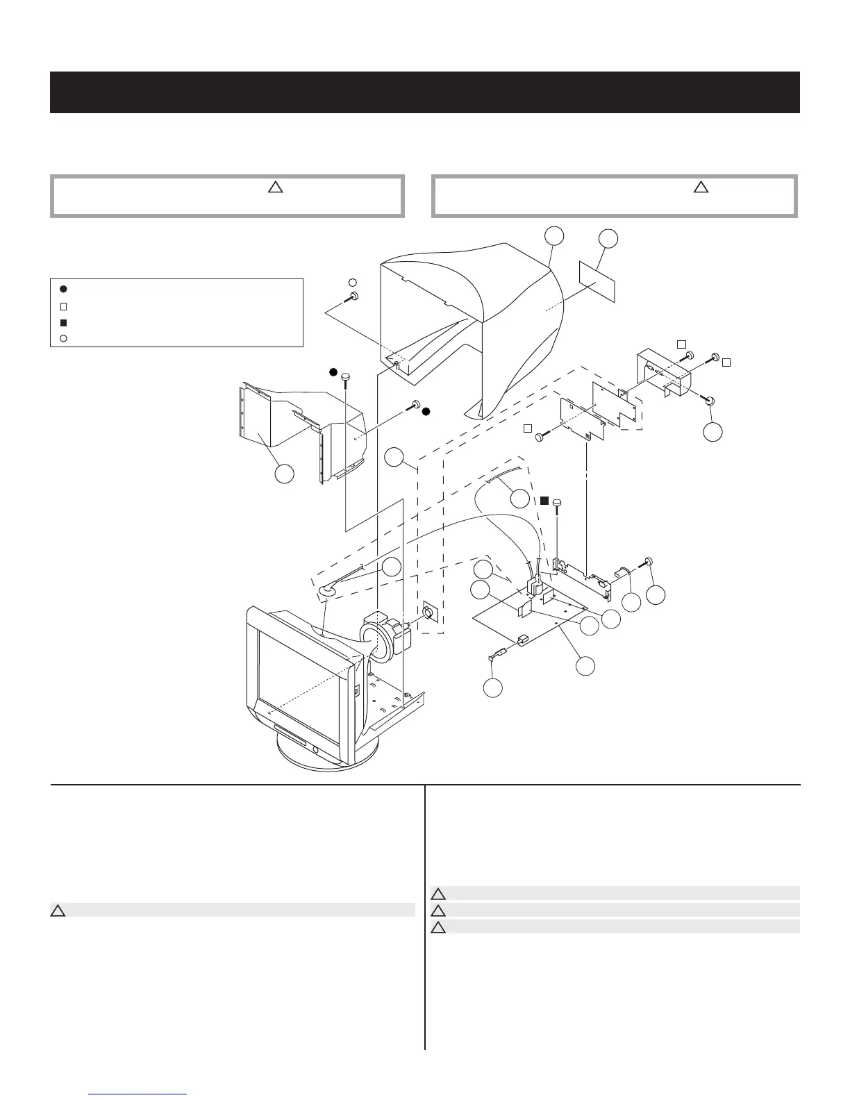
REF. NO. PART NO. DESCRIPTION REF. NO. PART NO. DESCRIPTION [ASSEMBLY INCLUDES]
SECTION 5: EXPLODED VIEW
* 1 A-1299-419-A A1 BOARD, COMPLETE
2 X-4038-603-3 SHIELD ASSY, EMI
3 4-080-941-91 CABINET
* 4 4-093-862-01 LABEL, INFORMATION
5 4-635-966-01 SCREW (HEX)
6 4-052-345-01 SCREW, (3X8) (+K), TAPPING
!
7 1-251-382-31 INLET, AC 3P(WITH NOISE FILTER)
* 8 A-1391-095-A N BOARD, MOUNTED
* 9 A-1391-119-A L2 BOARD, MOUNTED
* 10 A-1348-031-E D BOARD, COMPLETE
The high-voltage leads associated with the FBT on the D Board are not
included and must be ordered separately. (See 14-15)
11 4-079-799-01 BAR, EXTENSION
* 12 A-1333-007-A DA BOARD, MOUNTED
!
13 1-453-382-11 FBT ASSY/NX-4702//KQE4 (14-15)
!
14 1-900-805-55 WIRE ASSY, FOCUS LEAD
!
15 1-251-715-63 CAP ASSY, HIGH-VOLTAGE
5-1. CHASSIS
7-685-881-09 SCREW +BVTT 4X8 (S)
7-685-646-79 SCREW +BVTP 3X8 TYPE2 IT-3
7-685-647-79 SCREW +BVTP 3X10 TYPE2 TT(B)
7-685-663-71 SCREW +BVTP 4X16 TYPE2 IT-3
— 33 —
CPD-E530