CX-BK1
8
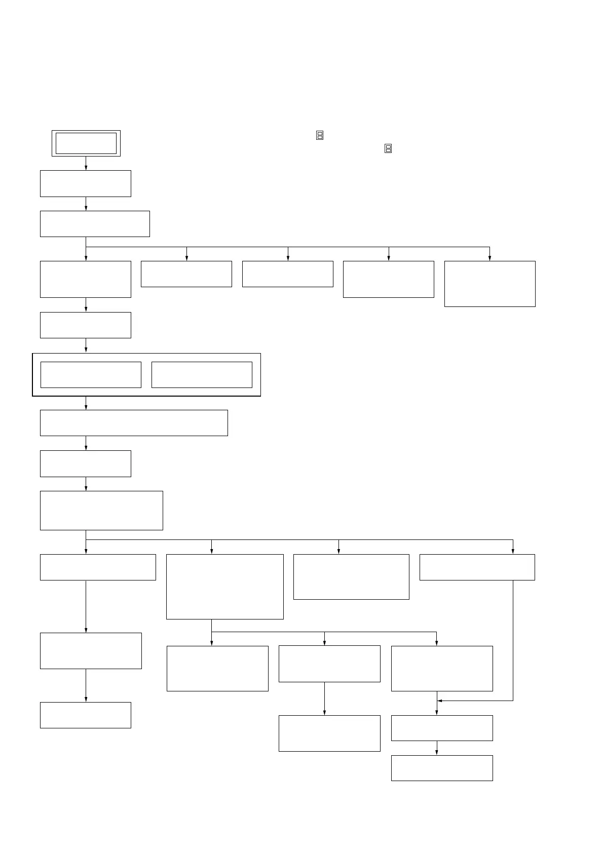
• This set can be disassembled in the order shown below.
3-1. DISASSEMBLY FLOW
SECTION 3
DISASSEMBLY
3-2. PANEL
(Page 9)
3-5. MAIN BOARD
(Page 110)
3-15. BD BOARD
(Page 15)
3-22. TIMING BELT
(FRONT/REAR)
(Page 19)
3-23. CAM (GEAR)
(Page 19)
3-24. SENSOR BOARD
(Page 20)
3-10. AMP BOARD
(Page 13)
3-11. CD MECHANISM DECK
(CDM69BV-30CBD64NS)
(Page 13)
3-13. BASE UNIT SECTION
(Page 14)
3-16. SW (1) BOARD,
SW (2) BOARD,
SW (3) BOARD,
SW (4) BOARD,
BRACKET (TOP) ASSY
(Page 16)
3-18. MOTOR (STOCKER)
ASSY (STOCKER)
(M761)
(Page 17)
3-17. CONNECTOR BOARD
(Page 16)
3-14. BASE UNIT
(BU-30CBD64NS)
(Page 15)
3-19. MOTOR (ROLLER)
ASSY (ROLLER)
(M781)
(Page 17)
3-21. RUBBER ROLLER
(SLIDER) ASSY
(Page 18)
3-20. MOTOR (MODE)
ASSY (MODE)
(M771)
(Page 18)
3-7. TUNER (FM/AM)
(Page 11)
3-8. SPEAKER BOARD
(Page 12)
3-4. FRONT PANEL
ASSY
(Page 10)
3-6. REAR COVER
(Page 11)
3-7. TUNER (FM/AM)
(Page 11)
3-8. SPEAKER
BOARD
(Page 12)
3-12. SIGNAL
CASSETTE
MECHANISM
(Page 14)
3-3. TOP PANEL BLOCK
(Page 9)
3-9. ACDC BOARD, POWER TRANSFORMER
(Page 12)
SET
Note 1: The process described in can be performed in any order.
Note 2: Without completing the process described in , the next process can not be performed.
Note 3: Tape deck is not loaded in US model.