4-1
SECTION 4
PRINTED WIRING BOARDS AND SCHEMATIC DIAGRAMS
THIS NOTE IS COMMON FOR PRINTED WIRING
BOARDS AND SCHEMATIC DIAGRAMS.
(In addition to this, the necessary mote is printed
in each block.)
For printed wiring boards:
• X : indicates a lead wire mounted on the component
side.
• x : indicates a lead wire mounted on the printed side.
• ® : Through hole.
• p : Parts mounted on the conductor side.
• b : Pattern from the side which enables seeing.
(The other layers’ patterns are not indicated.)
For schematic Diagram:
• Caution when replacing chip parts.
New parts must be attached after removal of chip.
Be careful not to heat the minus side of tantalum capacitor,
because it is damaged by the heat.
• All resistors are in ohms,
1
/
4
W (Chip resistors :
1
/
10
W)
unless otherwise specified.
kΩ : 1000Ω, MW : 1000kΩ.
• All capacitors are in µF unless otherwise noted. pF : µµF
50V or less are not indicated except for electrolytics and
tantalums.
• All variable and adjustable resistors have characteristic curve
B, unless otherwise noted.
• 2 : nonflammable resistor.
• 5 : fusible resistor.
• C : panel designation.
• ¢ : internal component.
• C : adjustment for repair.
• U : B+ Line.
• V : B– Line.
• Circled numbers refer to waveforms.
• Voltages are dc between measurement point.
• Readings are taken with a color-bar signals on DVD refer-
ence disc and when playing CD reference disc.
• Readings are taken with a digital multimeter (DC 10MW).
• Voltage variations may be noted due to normal production
tolerances.
Caution:
Pattern face side: Parts on the pattern face side seen from
(Side B) the pattern face are indicated.
Parts face side: Parts on the parts face side seen from
(Side A) the parts face are indicated.
When indicating parts by reference
number, please include the board
name.
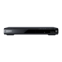
DVP-S7700
Note:The components identified by mark ! or dotted line
with mark ! are critical for safety.
Replace only with part number specified.
 Loading...