57
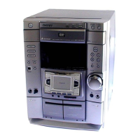
HCD-DP900D
Description
Pin NamePin No. I/O
51 NO-USE I Not used
52 B TRG O B deck trigger control signal output
53 AMS-IN I AMS signal input
54 CAPM-H/L O Capstan moter highi/low speed control signal output
55 CAPM-CNT 1 O Capstan moter REV/FWD/STOP control signal output
56 A PLAY I A deck play detect signal input
57 B PLAY I B deck play detect signal input
58 TC-MUTE O Tape deck line mute switch signal output. mute: “H”
59 R/PB/PAS I REC/PB/PASS select signal input
60 NR-ON/OFF O DOLBY NR on/off switch signal output
61 REC-MUTE O REC mute switch signal output (mute “L”)
62 VCC I Power supply(+5V)
63 SOFT-TEST O Soft out check point
64 VSS — Ground
65 BIAS O BIAS on/off switch signal output.
66 EQ-H/N O EQ high/low switch serect signal output
67 PB-A/B O A/B playback deck select signal output (deck A: “L”, deck B “H”)
68 ALC O ALC switch signal output (on: “L”, off “H”)
69 TC-RELAY O Tape deck relay switch signal output
70 A HALF I A deck half detect signal input
71 LINE-MUTE O Line mute signal output (on “H”, off “L”)
72 STK-POWER O Power amplifier on/off signal output (on “H”, off “L”)
73 DISPLAY KEY I Display key on/off switch signal input
74 POWER KEY I Power key on/off switch signal input
75 DIR-UNLOCK I Dir pll unlock signal input (analog: “H”, DVD/Din normal: “L”)
76 DIR-CS O Dir cs signal output (normal “H”)
77 DIR-XSTATE I Dir xstate signal input (normal “H”)
78 DIR-Rx I Dir tx signal input
79 CODEC-SMUTE I Codec soft mute signal input (normal “L”, mute “H”)
80 DSP-ACK I DSP ACK signal input
81 DSP-CS I DSP CS signal input
82 DSP-DECODE I DSP DECODE signal input (AC-3 DTS decode “H”)
83 STBY-RELAY O Main power on/off switch signal output
84 FRONT-RELAY O Front speaker relay switch signal output
85 REAR-RELAY O Not used (rear speaker relay)
86 SP PROTECT I Front speaker protect signal input ( on “L”)
87 STEREO I FM stereo detection signal input (stereo “L”)
88 TUNED I Tuning detection signal input (tuned “L”)
89 A SHUT I Shut off detection signal input (A deck reel pulse)
90 B SHUT I Shut off detection signal input (B deck reel pulse)
91 B-HALF I Detection input from the B deck half signal input
92 MODEL-IN I Destination setting terminal
93 SPEC-IN I Destination settnng terminal
94 FAN O Fan on control signal output
95 PWECK I Power check input
96 AVSS — Ground
97 POWER O Standby LED on/off control signal output
98 VREF I Reference voltage(+5V)
99 AVCC I Power supply (+5V)
100 AC-CUT I AC cut on/off check signal input