Do you have a question about the Sony HCD-DP900D and is the answer not in the manual?
Details power output, input/output voltages, and impedances.
Lists mechanism types for DVD and tape decks.
Describes laser type, frequency response, and signal-to-noise ratio.
Details recording system and frequency response for tape deck.
Covers FM/AM tuning ranges and intermediate frequencies.
Includes power requirements, dimensions, and accessories.
Highlights critical components for safe operation.
Advises on electrostatic discharge prevention for optical pick-ups.
Provides safety distance for checking laser diode emission.
Lists model names and corresponding parts numbers.
Describes error codes and corrective actions for system malfunctions.
Details service jig connections and optical pick-up replacement.
Procedures for initializing memory after MB board exchange.
Instructions to unlock the disc tray function.
Lists main unit parts in alphabetical order.
Step-by-step guide for setting the current time.
Outlines the general disassembly process.
Detailed steps for removing the top case.
Steps for removing the loading panel.
Steps for removing front panel and DVD mechanism.
Steps for removing the tape mechanism deck.
Steps for removing these boards.
Steps for removing the escutcheon pad assembly.
Steps for removing sub trans board, back panel, and fan.
Steps for removing trans and main boards.
Steps for removing amplifier boards.
Steps for removing head and leaf SW boards.
Steps for removing DSP, MB, and video boards.
Steps for removing RF-240 board and pick-up.
Steps for removing driver and associated boards.
Resets system data to factory default conditions.
Allows adjustment of AM channel step.
Switches between MD and VIDEO input modes.
Checks software version, LEDs, and keyboard operations.
Checks amplifier, tuner, and tape deck operations.
Describes the automated test sequence for the tape mechanism.
Describes the automated test sequence for the DVD mechanism.
Explains the format of DVD error history codes.
Sets DVD/CD player for shipping without clearing memory.
Sets DVD/CD player for shipping with memory cleared.
Explains the format of Blu-ray error history codes.
Controls the Variable Attenuation Control System.
Enables infinite playback repetitions.
Safety and best practices before performing adjustments.
Lists torque values for various tape deck mechanisms.
General guidelines for deck electrical adjustments.
Procedure to align the playback head for optimal signal.
Visual references for checking signal phase and output.
Procedure to adjust tape transport speed.
Procedure to set recording bias level.
Procedure to adjust recording signal level.
Procedure to adjust playback signal output level.
Adjusting FM signal sensitivity.
Steps to adjust circuit to zero voltage output.
When servo circuit components are replaced.
Adjusts video output level for NTSC standard.
Verifies S-Video output signal levels.
Explains symbols and conventions used in schematics.
Explains markings on printed wiring boards.
Diagram showing the physical placement of all internal boards.
Waveform examples for various ICs on the MB board.
Waveform examples for ICs on the RF-240 board.
Waveform examples for ICs on the Panel board.
Waveform examples for ICs on the Main board.
Overall functional block diagram of the Tuner and DVD DSP.
Functional block diagram of the DVD system.
Functional block diagram of the main audio/control section.
Component placement diagram for the RF-240 board.
Detailed electronic schematic for the RF-240 section.
Component placement diagram for the MB board (Side A).
Component placement diagram for the MB board (Side B).
Circuit diagram for the MB board, part 1 of 5.
Circuit diagram for the MB board, part 2 of 5.
Circuit diagram for the MB board, part 3 of 5.
Circuit diagram for the MB board, part 4 of 5.
Circuit diagram for the MB board, part 5 of 5.
Circuit diagram for the driver section.
Component layout for the driver section.
Component layout for the main section.
Circuit diagram for the main section, part 1 of 3.
Circuit diagram for the main section, part 2 of 3.
Circuit diagram for the main section, part 3 of 3.
Component layout for the DSP section.
Circuit diagram for the DSP section, part 1 of 2.
Circuit diagram for the DSP section, part 2 of 2.
Component layout for the OPT section.
Circuit diagram for the OPT section.
Component layout for the Front Amp section.
Circuit diagram for the Front Amp section.
Component layout for the Surround Amp section.
Circuit diagram for the Surround Amp section.
Component layout for the Panel section.
Circuit diagram for the Panel section, part 1 of 2.
Circuit diagram for the Panel section, part 2 of 2.
Component layout for the Leaf SW section.
Circuit diagram for the Leaf SW section.
Component layout for the Trans section.
Circuit diagram for the Trans section.
Detailed pin descriptions for the MB System Control IC.
Detailed pin descriptions for the Master Control IC.
Detailed pin descriptions for the Display Control IC.
Detailed pin descriptions for the Decoder IC.
Block diagram of the CXD9635R IC.
Block diagram of the IMIC6001BTD IC.
Block diagram of the µPC1330HA IC.
Block diagram of the AK4527 IC.
Block diagram of the BA7666FS-E2 IC.
Block diagram of the LC72131D IC.
Block diagram of the LA1845 IC.
Block diagram of the LC89056W-E IC.
Block diagram of the SP3728AC IC.
Exploded diagram of the main unit assembly and parts.
Exploded diagram of the front panel assembly.
Exploded diagram of the chassis assembly and related components.
Exploded diagram of the tape mechanism deck (Part 1).
Exploded diagram of the tape mechanism deck (Part 2).
Exploded diagram of the DVD mechanism deck.
List of components for the CD Panel Board.
List of components for the Driver Board.
List of components for the DSP Board.
List of capacitors used in the DSP section.
List of connectors used in the DSP section.
List of diodes used in the DSP section.
List of integrated circuits used in the DSP section.
List of coils used in the DSP section.
List of transistors used in the DSP section.
List of resistors used in the DSP section.
Continued list of resistors for the DSP section.
List of resistors used in the Front Amp section.
List of capacitors used in the Front Amp section.
List of connectors used in the Front Amp section.
List of diodes used in the Front Amp section.
List of transistors used in the Front Amp section.
Continued list of resistors for the Front Amp section.
List of components for the MB board.
List of components for the OPT IN board.
List of components for the Panel board.
List of components for the Head (B) board.
List of components for the Leaf SW board.
List of components for the Main board.
List of capacitors for the Main board.
List of connectors for the Main board.
List of filters for the Main board.
List of diodes for the Main board.
List of ICs for the Main board.
List of IF transformers for the Main board.
List of transistors for the Main board.
List of resistors for the Main board.
Continued list of resistors for the Main board.
Continued list of resistors for the Main board.
List of capacitors for the Main board.
List of connectors for the Main board.
List of capacitors for the MB board.
List of connectors for the MB board.
List of ferrite beads for the MB board.
List of filters for the MB board.
List of ICs for the MB board.
List of coils for the MB board.
List of transistors for the MB board.
List of resistors for the MB board.
Continued list of resistors for the MB board.
Continued list of resistors for the MB board.
List of components for the Panel board.
List of components for the RF-240 board.
List of components for the Sensor board.
List of resistors for the Panel board.
List of switches for the Panel board.
List of capacitors for the RF-240 board.
List of connectors for the RF-240 board.
List of diodes for the RF-240 board.
List of ICs for the RF-240 board.
List of coils for the RF-240 board.
List of transistors for the RF-240 board.
List of resistors for the RF-240 board.
List of switches for the RF-240 board.
List of components for the Sensor board.
List of components for the Trans board.
List of components for the Sub Trans board.
List of components for the Video board.
Continued list of parts for the Trans board.
Continued list of parts for the Video board.
Overview of the test mode functionality and usage.
Steps to enter the test mode and navigate the menu.
Details on checking system diagnosis items.
Verifies ROM revision, model type, and region codes.
Tests Gate Array and EEPROM for data integrity.
Evaluates Servo DSP and DSP Driver performance.
Verifies power supply and bus communication integrity.
Further tests for ARP to RAM address bus and RAM.
Tests RAM and SP functions within the AV Decoder.
Verifies video signal output using color bars.
Checks audio signal output for ARP and 1930 functions.
Comprehensive list of all available diagnostic tests.
Detailed explanation of all possible error codes.
Automated process for adjusting disc drive parameters.
Manual control of drive functions and adjustments.
Automated sequence for testing mechanism durability.
How to view and manage recorded emergency history data.
Detailed procedure for adjusting CD drive performance.
Detailed procedure for adjusting dual-layer DVD drive performance.
Detailed procedure for adjusting SACD drive performance.
Manually checks disc type and memory status.
Guide for selecting the correct disc type for operation.
Manual activation and deactivation of servo systems.
Options for automated mechanism aging tests.
Procedures for clearing laser hours and history logs.
Details on emergency codes and their meanings.
Shows ROM version, SYSCON version, and region codes.
Steps to adjust video output level using color bars.
Records changes and updates made to the service manual.
| Brand | Sony |
|---|---|
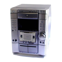
| Model | HCD-DP900D |
| Category | Stereo System |
| Language | English |