Do you have a question about the Sony HCD-DP800AV and is the answer not in the manual?
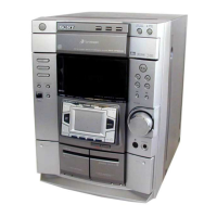
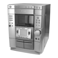
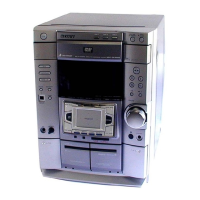
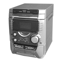
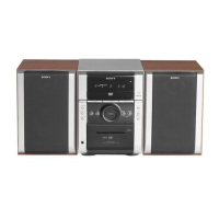
Identifies and lists components of the main unit.
Explains the function of each button on the main unit.
Procedure for removing the top case of the equipment.
Procedure for removing the loading panel and disc tray.
Procedure for disassembling the front panel and CD mechanism.
Procedure for removing the tape mechanism deck.
Procedure for disassembling the CD panel and related boards.
Procedure for removing the escutcheon pad with touch pad.
Procedure for removing DSP, SUB TRANS, back panel, fan, and OPT IN boards.
Procedure for disassembling the TRANS and MAIN boards.
Procedure for disassembling the FRONT AMP and SURROUND AMP boards.
Procedure for removing LEAF SW and HEAD boards.
Procedure for disassembling the base unit.
Procedure for disassembling driver, motor, and CD sensor boards.
Clears all data to initial conditions, resetting the set.
Changes AM channel step between 9 kHz and 10 kHz.
Checks software version, FL tube, LED, keyboard, and VACS.
Checks operations of Amplifier, Tuner, and Tape sections.
Checks tape deck and CD section operation.
Displays error history for the BD section.
Displays error history for the CDM58 CD mechanism.
Moves pickup to a durable position for vibration resistance.
Moves pickup to a durable position for vibration resistance.
Allows free running of the CD sled motor for cleaning.
Switches the VACS (Variable Attenuation Control System) ON/OFF.
Enables infinite repetitions for CD playback.
Important precautions before performing mechanical adjustments.
Details torque specifications and measurement procedures for tape decks.
Procedure for adjusting the azimuth of record/playback heads.
Procedure to adjust tape speed for Deck B.
Procedure to adjust playback level for both decks.
Procedure for adjusting the REC bias for Deck B.
Procedure for adjusting the REC level for Deck B.
Adjusts the FM tuned level for optimal reception.
Adjusts the FM circuit for null signal detection.
Checks the S-curve waveform for proper focus tracking.
Confirms the RF signal waveform and level.
Checks the E-F balance for 1 track jump function.
Shows the physical location of all circuit boards within the unit.
Illustrates the overall system architecture and signal flow.
Detailed schematic of the MAIN board, part 1/3.
Shows component layout on the MAIN board.
Lists pin functions for various ICs used in the unit.
Visual representation of IC internal logic and connections.
Exploded view of the main unit components.
Exploded view of the front panel assembly.
Exploded view of the chassis and related parts.
Exploded view of the tape mechanism deck, part 1.
Exploded view of the tape mechanism deck, part 2.
Exploded view of the CD mechanism deck.
Exploded view of the base unit assembly.
| Total Harmonic Distortion | 1% |
|---|---|
| Frequency Response | 20Hz - 20kHz |
| Speaker Impedance | 6 ohms |
| CD Player | Yes |
| Cassette Deck | Yes |
| Remote Control | Yes |
| Power Output | 100W |
| Radio Tuner | AM/FM |
| Outputs | Headphone Jack |
| Functions | CD Player, Radio Tuner, Cassette Deck |
| Speakers | 2-way bass reflex speakers |