HCD-EC709iP/EC909iP
6
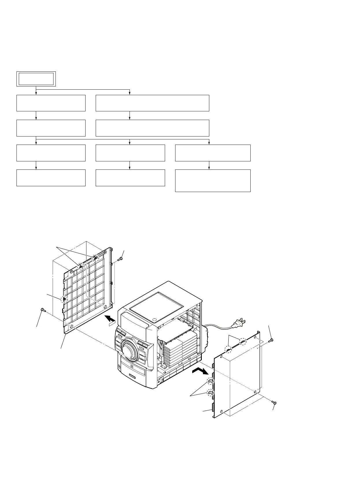
SECTION 2
DISASSEMBLY
• This set can be disassembled in the order shown below.
2-1. DISASSEMBLY FLOW
Note: Follow the disassembly procedure in the numerical order given.
2-2. SIDE PANEL (L)/(R)
SET
2-5. TOP PANEL BLOCK
(Page 8)
2-6. BACK PANEL BLOCK
(Page 9)
2-8. FRONT PANEL BLOCK
(Page 10)
2-10. BASE UNIT (BU-D1BD73)
(Page 11)
2-11. OPTICAL PICK-UP BLOCK
(DA11MMVGP)
(Page 11)
2-7. MAIN BOARD
(Page 9)
2-2. SIDE PANEL (L)/(R)
(Page 6)
2-3. ORNAMENT PLATE (DOCK) OR iPod ASSY
(Page 7)
2-4. IP BOARD BLOCK, BASE (DOCK) BLOCK
(Page 8)
2-9. KNOB (VOL)
(Page 10)
4
4
2
two screws
(BVTP3
u
10)
1
four screws
(case 3)
1
four screws
(case 3)
5
side panel (L)
5
side panel (R)
3
two claws
3
claw
3
two claws
3
two claws
2
two screws
(BVTP3
u
10)