11
HCD-EP404
SECTION 4
MECHANICAL ADJUSTMENTS
SECTION 5
ELECTRICAL ADJUSTMENTS
PRECAUTION
1. Clean the following parts with a denatured-alcohol-moistened
swab :
record/playback head pinch roller
erase head rubber belts
capstan idlers
2. Demagnetize the record/playback head with a head
demagnetizer.
3. Do not use a magnetized screwdriver for the adjustments.
4. After the adjustments, apply suitable locking compound to the
parts adjusted.
5. The adjustments should be performed with the rated power
supply voltage unless otherwise noted.
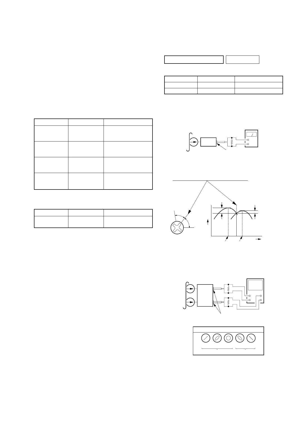
Torque Measurement
Tape Tension Measurement
Mode Torque Meter Meter Reading
FWD CQ-403A
more than 100 g
(more than 3.53 oz)
PRECAUTION
1. Setting
MEGA BASS switch : OFF
TAPE DECK SECTION 0 dB=0.775 V
Test tape
Mode Torque Meter Meter Reading
2.95 – 6.86 mN•m
FWD CQ-102C (30 – 70 g•cm)
(0.42 – 0.97 oz•inch)
0.15 – 5.39 mN•m
FWD
CQ-102C (1.5 – 5.5 g•cm)
Back Tension
(0.021 – 0.076 oz•inch)
more than 5.89 mN•m
FF CQ-201B (more than 60 g•cm)
(more than 0.83 oz•inch)
more than 5.89 mN•m
REW CQ-201B (more than 60 g•cm)
(more than 0.83 oz•inch)
Type Signal Used for
P-4-A100 10 kHz, –10 dB Head Azimuth Adjustment
WS-48B 3 kHz, 0 dB Tape Speed Adjustment
Record/Playback Head Azimuth Adjustment
Procedure:
1. Mode: Playback
level meter
test tape
P-4-A100
(10 kHz, –10 dB)
set
HEADPHONE board
PHONES jack (JK501
32
Ω
+
–
2. Turn the adjustment screw and check output peaks. If the peaks
do not match for L-CH and R-CH, turn the adjustment screw
so that outputs match within 1dB of peak.
3. Mode: Playback
4. After the adjustments, apply suitable locking compound to the
parts adjusted.
Screw
position
L-CH
peak
within
1dB
Output
level
L-CH
peak
R-CH
peak
within
1dB
Screw
position
R-CH
peak
test tape
P-4-A100
(10 kHz, –10 dB)
L-CH
R-CH
HEADPHONE board
PHONES jack (JK501)
oscilloscope
V
H
+
+
–
–
screen pattern
in phase
good wrong
45
°
90
°
135
°
180
°
32
Ω
32
Ω
set