19 19
3. Checking S Video Output S-C (DVD BOARD)
<Purpose>
This checks whether the S-C satisfies the NTSC Standard. If it is
not correct, the colors will be too dark or light.
Mode Video level adjustment in test mode
Signal Color bars
Test point CN005 pin 6
Instrument Oscilloscope
Specification 286 ± 50 mVp-p
Connection:
Checking method:
1) Confirm that the S-C burst is 286 ± 50 mVp-p.
Figure 5-3
286 ± 50 mVp-p
5
6
100µF
75Ω
±1%
100k
±1%
CN005
+
Oscilloscope
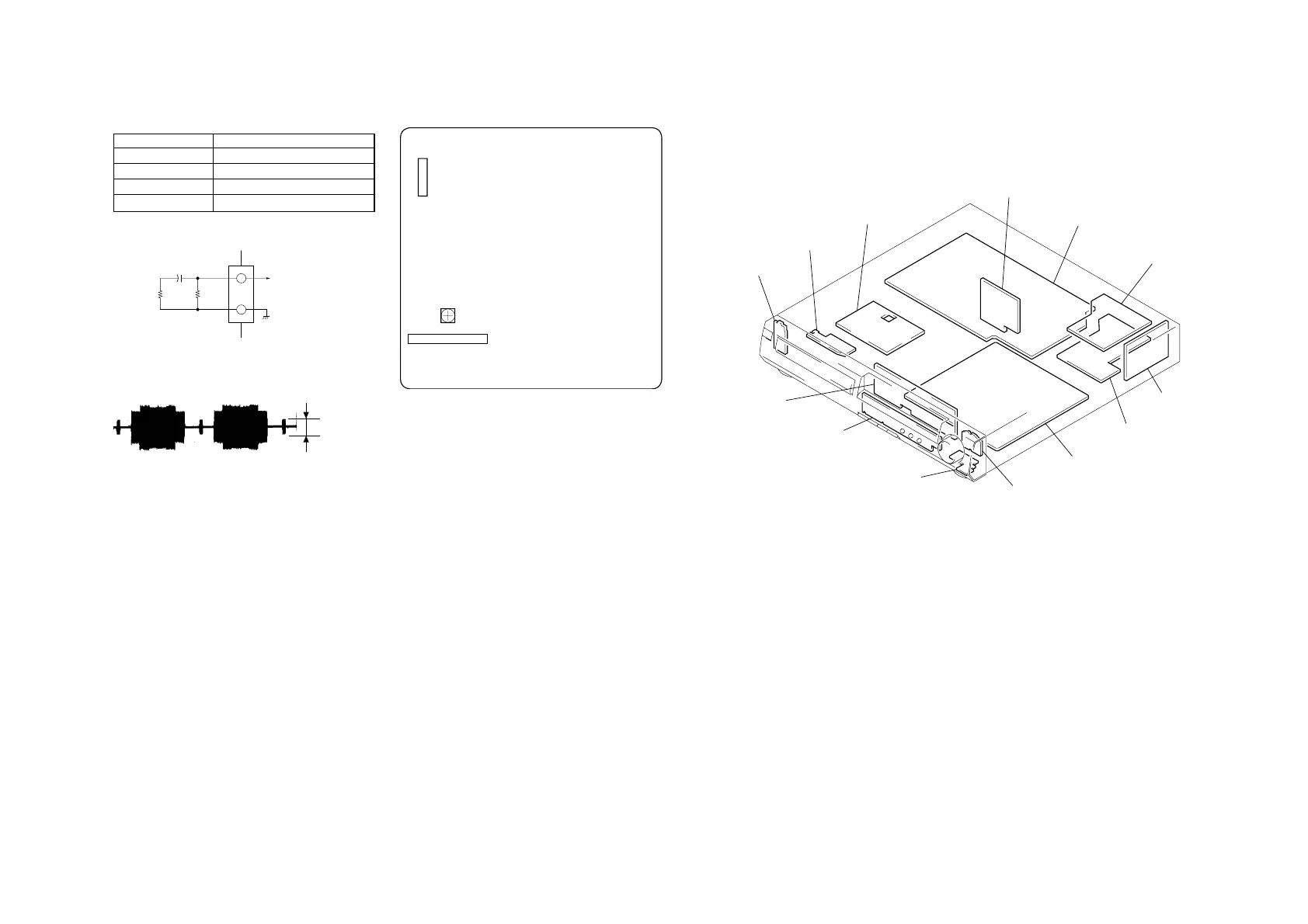
5-2. ADJUSTMENT RELATED PARTS
ARRANGEMENT
DVD BOARD (SIDE A)
12
76
CN005
RV401
VIDEO LEVEL ADJ
SECTION 6
DIAGRAMS
6-1.CIRCUIT BOARDS LOCATION
PW-932 board
FP-932 board
SW-932 board
HP-932 board
LV-932 board
DVD board
AUDIO board
TUNER board
VIDEO board
POWER board
PROTECT board
LOADING board
TK board

 Loading...