13
CD SECTION
Notes:
1. CD block basically constructed to operate without adjustment. There-
fore, check each item in order given.
2. Use YEDS-18 disc (Part No.: 3-702-101-01) unless otherwise indicated.
3. Use the oscilloscope with more than 10 MΩ impedance.
4. Clean an object lens by an applicator with neutral detergent when the
signal level is low than specified value with the following checks.
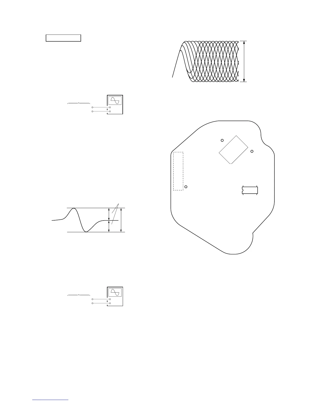
S-Curve Confirmation
Connection:
Procedure:
1. Connect an oscilloscope to IC703 pin !∞ and TP (VC) on the
CD board.
2. Connect between TP (FOK) and TP (GND) on the CD board
by lead wire.
3. Turn the power ON.
4. Press the
[EJECT] (CD) button to open the disc tray, and
put the disc (YEDS-18).
5. Press the
[EJECT] (CD) button to close the disc tray (Actu-
ate the focus search).
6. Confirm that the waveform on the oscilloscope is symmetrical
between A and B and that peak to peak level is within 3.0 ±
1.0 Vp-p.
S-curve waveform
7. After confirmation, disconnect the lead wire in step 2.
Note: • Try to measure several times to make sure that the ratio of A : B
or B : A is more than 10 : 7.
• Take sweep time as long as possible and light up the brightness
to obtain best waveform.
RF Level Confirmation
Connection:
Procedure:
1. Connect an oscilloscope to IC703 pin !§ and TP (VC) on the
CD board.
2. Turn the power ON.
3. Load the disc (YEDS-18), and press the
[] button to play-
back the disc.
4. Confirm that the waveform on the oscilloscope is clear and
that the RF signal level is correct.
Note: Clear RF signal waveform means that the shape “≈” can be clearly
distinguished at the center of the waveform.
+
–
CD board
IC703 pin
!∞
TP (VC)
oscilloscope
+
–
CD board
IC703 pin
!§
TP (VC)
oscilloscope
(AC range)
RF signal waveform
When observing the eye pattern, set the oscilloscope for AC range
and raise vertical sensitivity.
Connecting Location:
– CD Board (Conductor Side) –
VOLT/DIV: 200 mV
TIME/DIV: 500 ns
(with the 10: 1 probe
in use)
level: 1.3 Vp-p
+0.25
–0.20
6
6
within 3.0 ± 1.0 Vp-p
A
B
symmetry
 Loading...