18
HCD-VX333
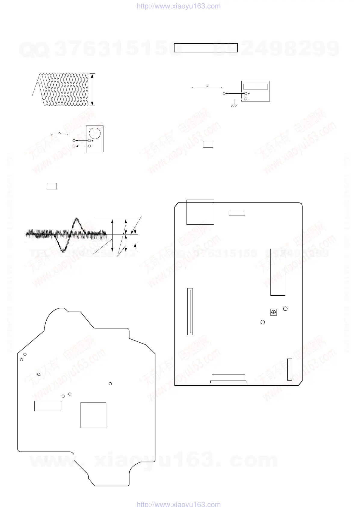
Note : Clear RF signal waveform means that the shape “ ◊ ” can be clearly
distinguished at the center of the waveform.
E-F Balance (1 Track jump) Check
Procedure :
1. Connect oscilloscope to TP (TE0) and TP (VC).
2. Turned Power switch on.
3. Load a disc (YEDS-18) and playback the number five track.
4. Press the gG button. (Becomes the 1 track jump mode.)
5. Confirm that the level B and A (DC voltage) on the oscilloscope
waveform.
6. After check, remove the lead wire connected in step 1.
RF signal waveform
VOLT/DIV : 200mV
TIME/DIV : 500ns
level : 1.45 ± 0.3Vp-p
TP(TE0)
TP(VC)
BD board
oscilloscop
level=1.3±0.6Vp-p
symmetry
A (DC voltage
center of
waveform
B
0V
1 track jump waveform
Specified level: –– × 100=less than ±22%
B
A
Adjustment Location : BD board
[BD BOARD] (Conductor Side)
TP (RF)
TP (VC)
IC103
IC101
TP (TE0)
TP (FE0)
TP (AGCCOM)
TP (DGND)
VIDEO CD SECTION
Frequency Adjustment
Connection:
Procedure:
1. Connect the frequency counter to check point of the VIDEO
board.
2. Turned power switch on.
3. Press the CD button to select the CD.
4. Adjust CT503 on the VIDEO board so that the frequency counter
reading 27.0 MHz ± 80 Hz at stop status.
Adjustment Location : VIDEO CD board
[VIDEO CD BOARD] (Component Side)
VIDEO board
(27 MHz)
frequency counte
J301
CN501
CN503
CN502
IC507
(GND)
(27MHz)
CT503
VIDEO
Frequency
Adjustment
CN301
w
w
w
.
x
i
a
o
y
u
1
6
3
.
c
o
m
Q
Q
3
7
6
3
1
5
1
5
0
9
9
2
8
9
4
2
9
8
T
E
L
1
3
9
4
2
2
9
6
5
1
3
9
9
2
8
9
4
2
9
8
0
5
1
5
1
3
6
7
3
Q
Q
TEL 13942296513 QQ 376315150 892498299
TEL 13942296513 QQ 376315150 892498299
http://www.xiaoyu163.com
http://www.xiaoyu163.com