Do you have a question about the Sony HCD-VX777 and is the answer not in the manual?
Details on video CD and CD player system, laser, output, frequency response, S/N ratio, dynamic range.
Procedure for removing the top case, including screw and claw locations.
Steps to remove the loading panel, involving pulley and disc tray.
Procedure for removing the front panel section, detailing screws and connectors.
Steps to remove the tape mechanism deck, showing screws and claws.
Procedure for removing CD SW, panel, and pad switch boards, including screws and claws.
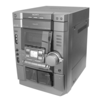
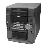
Overview of the front panel controls, buttons, and indicators with their locations.
Steps to remove the main trans board, showing screws, connectors, and sensor board.
Procedure for removing the main and power boards, including heat sink and connectors.
Clears all RAM data to initial conditions. Used when returning the set to the customer.
Resets the set with preset data retained in memory, similar to power cycling.
Checks software version, FL tube, LED, keyboard, and VACS. Includes version display and key check modes.
Measurement of torque for FWD/REV back tension, FWD tension, and REV tension.
Procedure for adjusting azimuth for record/playback heads on Deck A and Deck B using test tape.
Procedure for adjusting tape speed on Deck B using WS-48B tape and a frequency counter.
Procedure for adjusting playback level for Deck A and Deck B using P-4-L300 tape and a level meter.
Procedure to adjust the video board frequency counter reading to 27MHz ± 80Hz.
Diagrams showing the location of various circuit boards within the main unit.
Notes on schematic diagram conventions for capacitors, resistors, lines, and critical components.
Notes on printed wiring board conventions for component side extraction and transistor indication.
Diagrams of waveforms for IC101 (XTAO, TE, RFAC, FE) during CD PLAY MODE.
Diagrams of waveforms for IC502 (XOUT), IC505 (COUT, YOUT), and IC304 (COUT, YOUT) on the video board.
Diagrams of waveforms for IC501 (XC-OUT, XOUT, BCK, LRCK) and T301 on the main board.
Exploded view of the main section, showing assembly of chassis, front panel, and CD mechanism.
Exploded view of the front panel assembly, detailing knobs, springs, and indicator tube.
Exploded view of the chassis, showing mounting of PC boards, transformer, and wiring.
Exploded view of the tape mechanism deck, showing pinch levers, heads, solenoids, and pulleys.
Exploded view of the tape mechanism deck, showing flywheels, bases, springs, and motors.
Exploded view of the CD mechanism deck, detailing screws, boards, motors, and gears.
Exploded view of the base unit, showing the BD board, gears, and precision screws.
Notes on parts list conventions, standardization, stocked items, and component identification.
| Brand | Sony |
|---|---|
| Model | HCD-VX777 |
| Category | Car Receiver |
| Disc Player | Yes |
| CD Player | Yes |
| MP3 Playback | Yes |
| USB Port | No |
| Auxiliary Input | Yes |
| Bluetooth | No |
| Remote Control | Yes |
| Display Type | LCD |
| Equalizer | Yes |
| Tuner Bands | FM/AM |