18
HCD-VX777
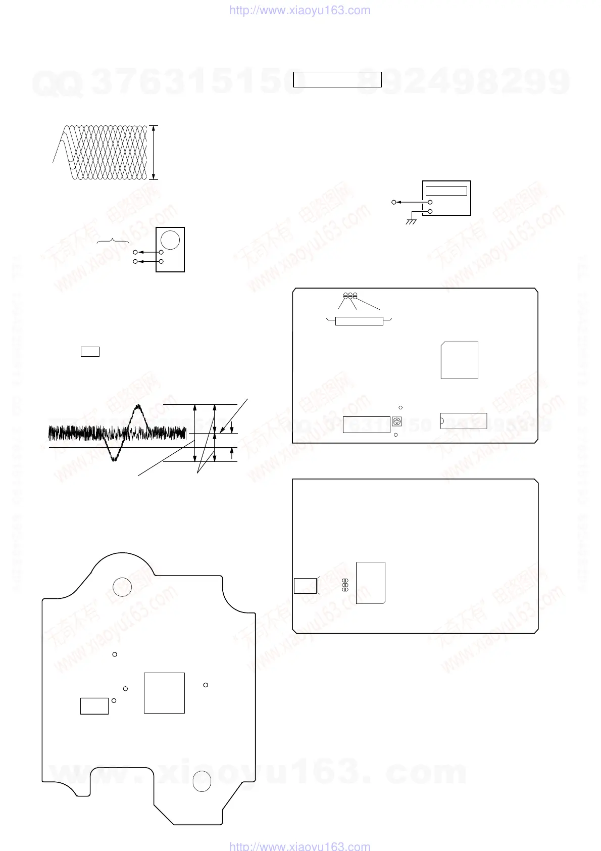
Note: Clear RF signal waveform means that the shape “◊” can be
clearly distinguished at the center of the waveform.
RF signal waveform
E-F Balance (1 Track jump) Check
Procedure:
1. Connect oscilloscope to TP (TEO) and TP (DVC) board.
2. Turned Power switch on.
3. Load a disc (LUV-P01) and playback the number nine track.
4. Press the bB button. (Becomes the 1track jump mode.)
5. Confirm that the level B and A (DC voltage) on the oscilloscope
waveform.
1 track jump waveform
6. Adjust RV101 so that A (DC voltage) becomes 0.
VOLT/DIV : 200mV
TIME/DIV : 500ns
level : 0.65 ± 0.15Vp-p (RFDC)
1.1 ± 0.4Vp-p (RFAC)
oscilloscope
BD board
TP (TEO)
TP (DVC)
+
–
DVC
Center of
waveform
B
Symmetry
A (DC voltage)
level=1.0±0.5Vp-p
Checking Location:
[BD BOARD]
IC103
IC101
TP
(RFDC)
TP
(CE)
TP
(RFAC)
TP
(XPCK)
VIDEO SECTION
Frequency adjustment
1. Connect the frequency counter to check point of the VIDEO
board.
2. Adjust CT503 of the VIDEO board so that the frequency
counter read 27MHz ± 80Hz at STOP condition.
[ VIDEO BOARD ] – SIDE B –
Adjustment Location :
[ VIDEO BOARD ] – SIDE A –
frequency counte
VIDEO board
(27 MHz)
+
–
SL501
IC502
SL502
SL503
TEST
MODE
SL501
SL502
CT503
SL503
TEST MODE
VIDEO
FREQUENCY
(27MHz)
(GND)
IC507
IC505
w
w
w
.
x
i
a
o
y
u
1
6
3
.
c
o
m
Q
Q
3
7
6
3
1
5
1
5
0
9
9
2
8
9
4
2
9
8
T
E
L
1
3
9
4
2
2
9
6
5
1
3
9
9
2
8
9
4
2
9
8
0
5
1
5
1
3
6
7
3
Q
Q
TEL 13942296513 QQ 376315150 892498299
TEL 13942296513 QQ 376315150 892498299
http://www.xiaoyu163.com
http://www.xiaoyu163.com