2
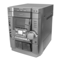
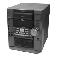
HCD-VX777
TABLE OF CONTENTS
1. GENERAL ·········································································· 4
2. DISASSEMBLY
2-1. Case (Top) ·········································································· 5
2-2. Loading PANEL ································································· 6
2-3. Front PANEL Section ························································· 6
2-4. Tape Mechanism Deck ······················································· 7
2-5. CD SW Board, PANEL Board, Pad Switch Board············· 7
2-6. MAIN Trans Board····························································· 8
2-7. MAIN Board, Power Board················································ 8
2-8. LEAF SW Board, Head (A) Board, Head (B) Board ········· 9
2-9. Base Unit ············································································ 9
2-10. DRIVER Board, Motor Board, CD Sensor Board and
VIDEO Board··································································· 10
3. TEST MODE···································································· 11
4. MECHANICAL ADJUSTMENTS ····························· 13
5. ELECTRICAL ADJUSTMENTS ······························· 13
6. DIAGRAMS
6-1. Circuit Board Location ····················································· 19
6-2. Block Diagrams ································································ 21
6-3. Schematic Diagram – BD Section – ································· 24
6-4. Printed Wiring Board – BD Section – ······························ 25
6-5. Printed Wiring Board – VIDEO Section – ······················· 26
6-6. Schematic Diagram – VIDEO (1/3) Section – ················· 27
6-7. Schematic Diagram – VIDEO (2/3) Section – ················· 28
6-8. Schematic Diagram – VIDEO (3/3) Section – ················· 29
6-9. Printed Wiring Boards – MAIN Section – ······················· 30
6-10. Schematic Diagram – MAIN (1/4) Section – ··················· 31
6-11. Schematic Diagram – MAIN (2/4) Section – ··················· 32
6-12. Schematic Diagram – MAIN (3/4) Section – ··················· 33
6-13. Schematic Diagram – MAIN (4/4) Section – ··················· 34
6-14. Schematic Diagram – SWITCH Section – ······················· 35
6-15. Printed Wiring Boards – SWITCH Section –··················· 35
6-16. Printed Wiring Boards – POWER AMP Section –··········· 36
6-17. Schematic Diagram – POWER AMP Section – ··············· 37
6-18. Printed Wiring Boards – PANEL Section –······················ 38
6-19. Schematic Diagram – PANEL Section – ·························· 39
6-20. Printed Wiring Boards – CD SW/PAD Section – ············· 40
6-21. Schematic Diagram – CD SW/PAD Section – ················· 41
6-22. Printed Wiring Boards – LEAF SW Section – ················· 42
6-23. Schematic Diagram – LEAF SW Section – ····················· 43
6-24. Printed Wiring Boards – DRIVER Section – ··················· 44
6-25. Schematic Diagrams – DRIVER Section – ······················ 45
6-26. Printed Wiring Boards – TRANS Section – ····················· 46
6-27. Schematic Diagram – TRANS Section – ························· 47
6-28. IC Pin Functions ······························································· 48
6-29. IC Block Diagrams ··························································· 57
7. EXPLODED VIEWS
7-1. MAIN Section ·································································· 61
7-2. Front PANEL Section ······················································· 62
7-3. Chassis Section ································································· 63
7-4. Tape Mechanism Section-1 (TCM-230MWR41)············· 64
7-5. Tape Mechanism Section-2 (TCM-230AWR41)·············· 65
7-6. CD Mechanism Deck Section (CDM58E-30BD61A) ····· 66
7-7. Base Unit Section (BU-30BD61A) ·································· 67
8. ELECTRICAL PARTS LIST ······································· 68
General
Power requirements
Australian models: 230 — 240 V AC,
50/60 Hz
Mexican models: 120 V AC, 60 Hz
Thailand models: 220 V AC, 50/60 Hz
Other models: 120 V, 220 V or
230 — 240 V AC,
50/60 Hz
Adjustable with voltage
selector
Power consumption
HCD-VX777 250 watts
Dimensions (w/h/d)
HCD-VX777 Approx. 280 x 360 x 425 mm
Mass :
HCD-VX777 Approx. 11 kg
Supplied accessories: AM loop antenna (1)
Remote commander (1)
Batteries (2)
Video cable (1)
FM lead antenna (1)
Front speaker pads (8)
(MHC-VX777 only)
Design and specifications are subject to change without notice.
w
w
w
.
x
i
a
o
y
u
1
6
3
.
c
o
m
Q
Q
3
7
6
3
1
5
1
5
0
9
9
2
8
9
4
2
9
8
T
E
L
1
3
9
4
2
2
9
6
5
1
3
9
9
2
8
9
4
2
9
8
0
5
1
5
1
3
6
7
3
Q
Q
TEL 13942296513 QQ 376315150 892498299
TEL 13942296513 QQ 376315150 892498299
http://www.xiaoyu163.com
http://www.xiaoyu163.com