3-2
S MIC Chassis
3-2. LANDING ADJUSTMENT
3-2-1. Preparations
1. To reduce geomagnetism effects, face the CRT screen
to the east or west.
2. Turn on the power switch, and erase the magnetic force
using a degausser.
3-2-2. Landing Adjustment
1. Receive the white signal, and set the CONTR and
BRIGHT controls as follows:
CONTR: MAXIMUM
BRIGHT: set easy to observe
2. Adjust the white balance, screen (G2) voltage, and
convergence roughly.
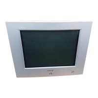
3. Loosen the deflection yoke mounting screw, and set the
purity control to the center as shown in Fig. 3-1.
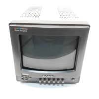
4. Set the test signal generator to green.
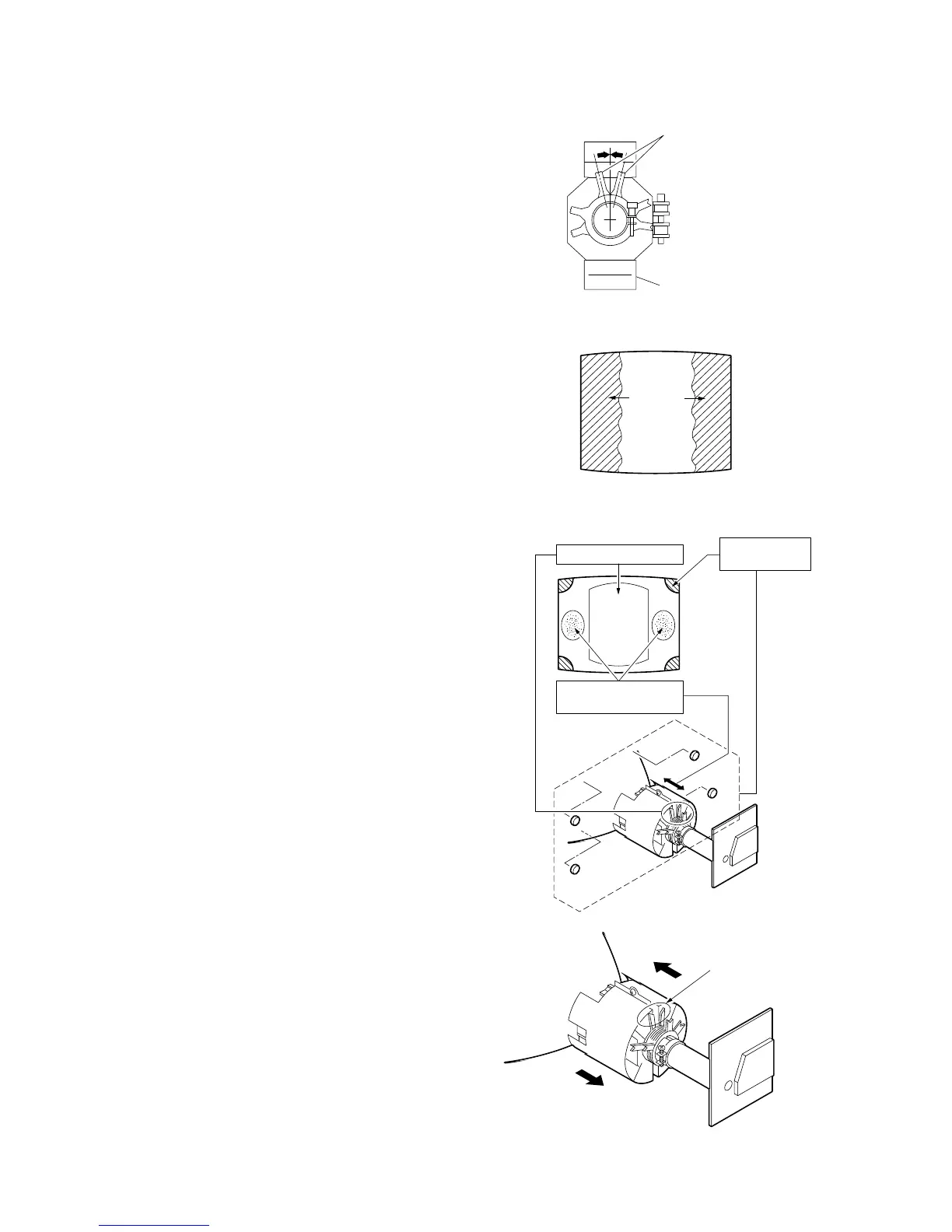
5. Move the deflection yoke backward, and adjust the
purity control so that the green is in the center and blue
and red are at the sides, evenly. (See Fig. 3-2.)
6. Move the deflection yoke forward, and adjust so that
the entire screen becomes green.
(Repeat steps 4 to 7 as to red and blue.)
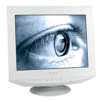
7. When the landing at the corners is not right, correct by
using the magnet. (See Fig. 3-3.)
Note: When correction magnet is used, be sure to
degauss the unit.
8. When the position of the deflection yoke is determined,
tighten it with a deflection yoke mounting screw.
Fig. 3-1
Fig. 3-2
Fig. 3-3
Deflection yoke
Purity control
Blue Red
Green
Disc magnet
correction area
a
a
d
d
c
c
b
b
Purity correction area
Deflection yoke
correction area
Step 6
Steps 3 and 5
Step 5
 Loading...