5-3
S MIC Chassis
5-1-6. Horizontal Deflection System Adjustment
(RV508, RV509, RV511, RV514, RV515,
and RV801/P Board)
Input signal: Monoscope signal
Switches: UNDER SCAN8 Pull (OFF)
16 : 9 8 Pull (4 : 3)
Controls: BRIGHT 8 50 % (Center click)
CONTR 8 70 %
1. Adjust the horizontal position with RV801 (H.CENT).
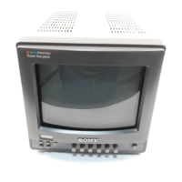
2. Adjust RV511 (H.SIZE) so that the horizontal size of
monoscope signal on the CRT screen is 16 frames.
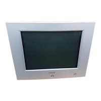
3. While adjusting vertical angular and bow distortions
with RV514 (V.ANG) and RV515 (BOW), adjust
RV509 (PIN AMP) and RV508 (PIN PHASE) so that
the vertical lines become straight.
5-1-7. Under Scan Adjustment (RV517, RV512)
Input signal: Monoscope signal
Switches: UNDER SCAN8 Push (ON)
16 : 9 8 Pull (4 : 3)
Controls: BRIGHT 8 50 % (Center click)
CONTR 8 70 %
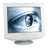
1. Adjust the horizontal size and vertical size with RV517
(U/V.SIZE) and RV512 (U/H.SIZE) as shown below.
Note: Be careful not to wane four corners.
5-1-8. Horizontal/Vertical Delay Adjustment
(RV832, RV831)
Input signal: Monoscope signal
Switches: UNDER SCAN8 Push (ON)
16 : 9 8 Pull (4 : 3)
Controls: BRIGHT 8 50 % (Center click)
CONTR 8 70 %
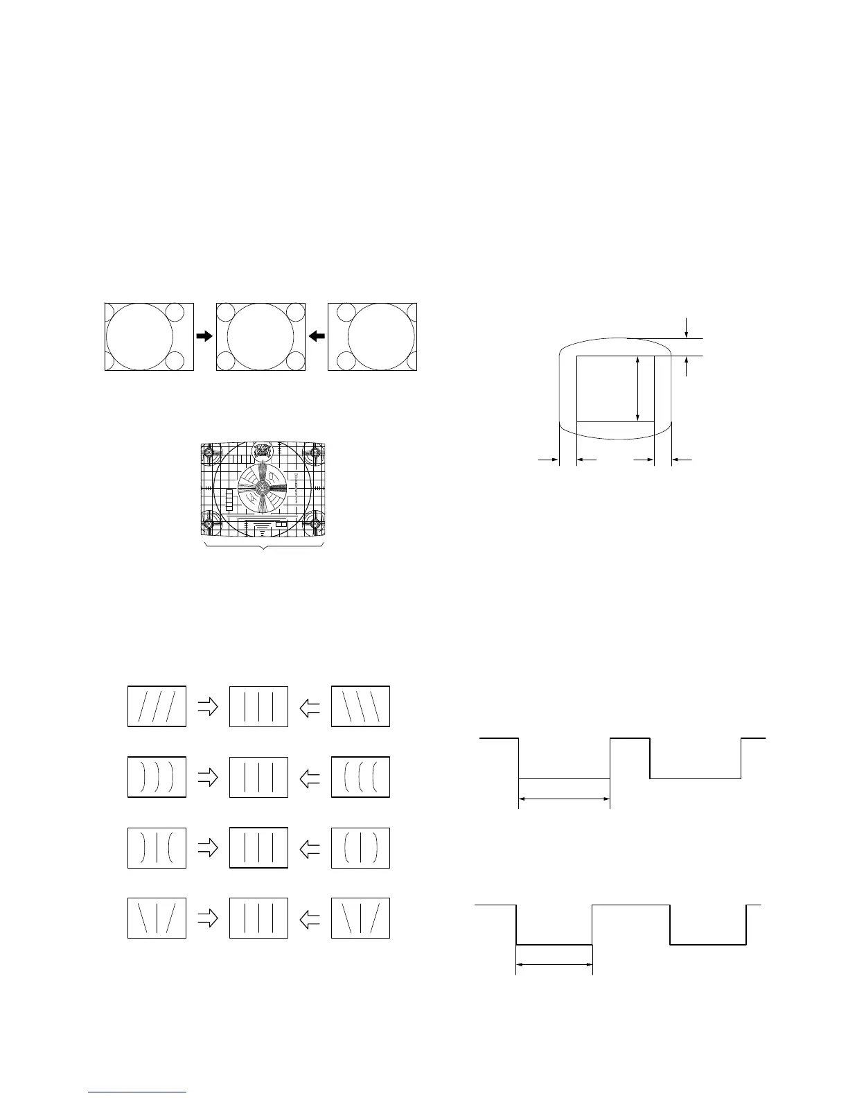
1. Connect an oscilloscope to pin 4 of IC831.
2. Horizontal Delay Adjustment (RV832)
Adjust the pulse width with RV832 as shown below.
3. Connect an oscilloscope to pin 9 of IC831.
4. Vertical Delay Adjustment (RV831)
Adjust the pulse width with RV831 as shown below.
16 frames
Screen center
Screen
center
4 ±1 mm
Monoscope
under scan
area
6 ±1 mm6 ±1 mm
BOW (RV515)
V.ANGLE (RV514)
PIN PHASE (RV508)
PIN AMP (RV509)
4. Adjust RV511 (H.SIZE) so that the horizontal size of
monoscope signal on the CRT screen is 16 frames.
41 ±1 uSec
IC831
PIN-4
8.0 ±0.4 mSec
IC831
PIN-9
 Loading...