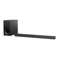
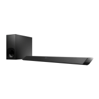
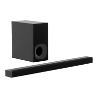
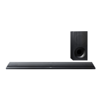
HT-NT3
HT-NT3
2727
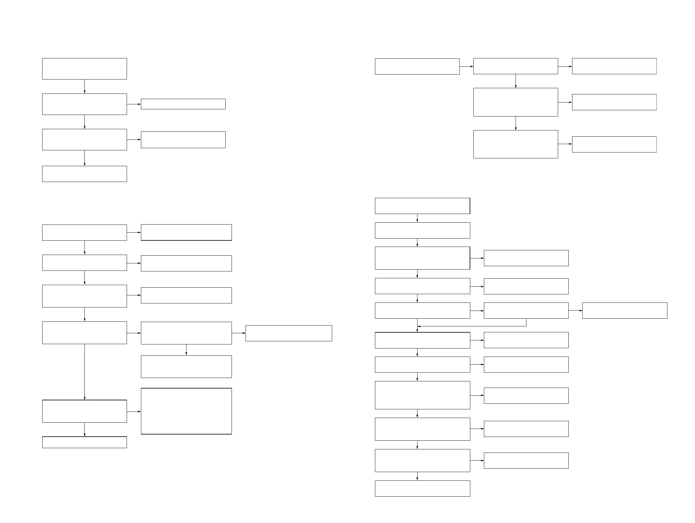
3. The sound is not outputted
Check that the signal is input to
AMP board IC6002 pin 24 and 27.
The sound is not outputted.
Yes
Yes
Change FFC insert to AMP Board
CN6004.
No
Exchange AMP board IC6002
(6-718-105-01)
No
Exchange AMP board IC6001
(6-721-742-01)
No
Yes
Check that the PWM signal is
outputted from the following pins.
AMP board IC6002 pin 38, 39, 40,
41, 48 and 49.
Check that the signal is outputted
from AMP board IC6001
pin 27, 28 and 32 (SP FRONT R)
pin 35, 39 and 40 (SP FRONT L)
4. Power is not turned on
Reprogram IF - con.
The voltage of the following is 20V/32V
SWITCHING REGULATOR (3L405W):
CN101 pin 2 to 4 and 8.
Check pin 1 of CN301 in MB-1407 board.
Check pin 3 of CN703 in MB-1407
board.
Yes
Power is not turned on.
Yes
Yes
Check AMP board CN6007 pin 2 is 12V.
Yes
Yes
Yes
Yes
Yes
Yes
Check MB-1407 board IC3004 pin 1
Yes Yes
Replace the SWITCHING
REGULATOR (3L405W).
No
No
No
Check X3001 on the MB-1407 board
whether is oscillating or not after AC IN.
Replace MB-1407 board.
No
Replace MB-1407 board.
Replace MB-1407 board.
No
No
Power supply IC is damaged.
Exchange the power supply IC.
No
Check the reset signal of pin 49 of
IC3004 on MB-1407 board during AC IN
or power on (there is a quick low pulse
to indicate reset signal).
Check PCONT1: pin 119
Check PCONT3: pin 123
Check SPARTA_PCONT: pin 65
Check each voltage with reference
to the schematic diagram and check
that there is no problem in them.
Check the related IC on MB-1407 board.
No
Replace MB-1407 board.
Replace MB-1407 board.
No
Check IC6003 funtion.
SECTION 4
TROUBLESHOOTING
1. “PRTECT” is displayed on the fl uorescent indicator tube after turning the power on
2. The video of HDMI is not displayed normally
“PRTECT” is displayed on the
fluorescent indicator tube after
turning the power on.
Yes
Check that AMP board IC6001
pin 27, 28, 32, 35, 39 and 40 is
short to GND.
No
Check and replace the speaker.
"PRTECT" is not displayed, when
removing the speaker and turning
the power on.
Yes
Yes
Exchange AMP board IC6001
(6-721-742-01)
AMP board damage. Exchange
complete AMP board.
No
Check that each power supply is
supplied.
Check that only the digital output
(HDMI) is affected.
Check that the input voltage of the
following pin is around 7.4V - 8V.
MB-1407 board IC5014 pin 5 (VIN).
Check that the output voltage of the
following pin is 5V. MB-1407 board
IC5014 pin 4 (VOUT).
Check that there are no
abnormalities in MB-1407 board
CN5012.
Perform other analyses.
Refer to the "Power is not turned
on" on page 27.
Check the settings on the menu
screen.
Refer to the "Power is not turned
on" on page 27".
Check that the input voltage of the
following pin is 3.3V. MB-1407
board IC5014 pin 1 (CONT).
Exchange the MB-1407 board IC5014.
Part No. : 6-718-999-01
Description: IC MM1839A50NRE
Exchange the MB-1407 board CN5012.
Note: When CN5012 is exchange, be
careful of the quality of soldering
enough.
Part No. : 1-821-398-41
Description: HDMI CONNECTOR
(HDMI OUT ARC HDCP 2.2)
Refer to the "Power is not turned
on" on page 27".
Yes
Yes
Yes
Yes
Yes
Yes
No
No
No
No No
No
 Loading...