HT-NT3
5
SECTION 1
SERVICING NOTES
UNLEADED SOLDER
Boards requiring use of unleaded solder are printed with the lead-
free mark (LF) indicating the solder contains no lead.
(Caution: Some printed circuit boards may not come printed with
the lead free mark due to their particular size)
: LEAD FREE MARK
Unleaded solder has the following characteristics.
• Unleaded solder melts at a temperature about 40 °C higher
than ordinary solder.
Ordinary soldering irons can be used but the iron tip has to be
applied to the solder joint for a slightly longer time.
Soldering irons using a temperature regulator should be set to
about 350 °C.
Caution: The printed pattern (copper foil) may peel away if
the heated tip is applied for too long, so be careful!
• Strong viscosity
Unleaded solder is more viscous (sticky, less prone to fl ow)
than ordinary solder so use caution not to let solder bridges
occur such as on IC pins, etc.
• Usable with ordinary solder
It is best to use only unleaded solder but unleaded solder may
also be added to ordinary solder.
ADVANCE PREPARATION WHEN CONFIRMING OP-
ERATION
All of the units included in the HT-NT3 (SA-NT3/SA-WNT3) are
required to confi rming operation of SA-NT3. Check in advance
that you have all of the units.
NOTE OF PERFORMING THE OPERATION CHECK IN
THE STATE THAT HEAT SINK WAS REMOVED
When performing the operation check in the state that this unit was
disassembled, it is possible to perform the operation check in the
state that heat sink was removed. But don’t perform the operation
check in the long time, and perform the operation check in the
volume state as low as possible.
NOTE OF REPLACING THE IC101, IC102, IC103,
IC301, IC302, IC303, IC410, IC3004 AND IC5010 ON
THE MB-1407 BOARD
IC101, IC102, IC103, IC301, IC302, IC303, IC410, IC3004 and
IC5010 on the MB-1407 board cannot replace with single. When
these parts are damaged, replace the complete mounted board.
NOTE OF REPLACING THE IC1501 ON THE WS
CHUKEI BOARD
IC1501 on the WS CHUKEI board cannot replace with single.
When this part is damaged, replace the complete mounted board.
NOTE OF REPLACING THE IC102 AND IC103 ON
THE MB-1407 BOARD
Replacement of IC102 and IC103 on the MB-1407 board used in
this unit requires a special tool.
“PRTECT (PROTECT)” APPEARS ON THE DISPLAY OF
THE BAR SPEAKER
q Press the ÒÄÆ (on/standby) button to turn off the system. After the
indicator disappears, disconnect the AC power cord (mains lead)
then check that nothing is blocking the ventilation holes of the
system.
NOTE OF REPLACING THE IC6001 ON THE AMP
BOARD AND THE COMPLETE AMP BOARD
When IC6001 on the AMP board and the complete AMP board are
replaced, it is necessary to spread the compound between the AMP
board and the heat sink.
Spread the compound (THERMAL COMPOUND (G747)) refer-
ring to the fi gure below.
– AMP Board (Component Side) –
IC6001
thermal compound (G747)
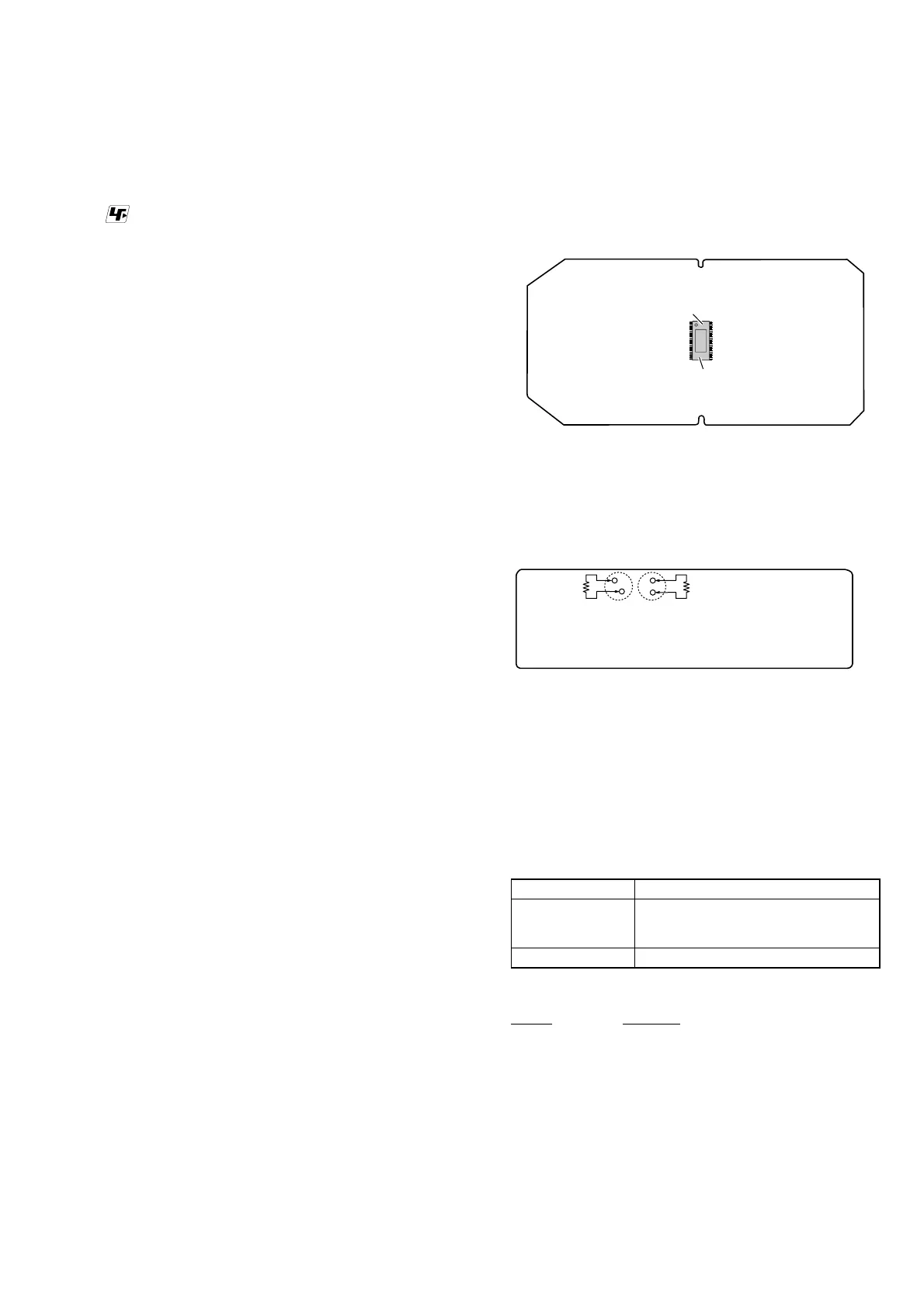
CAPACITOR ELECTRICAL DISCHARGE PROCESSING
When checking the board, for the electric shock prevention, con-
nect the resistors to both ends of respective capacitor (C201 and
C207) to discharge the capacitor (C201 and C207).
– SWITCHING REGULATOR (3L405W) Board
(Conductor Side) –
C207
C201
800 :/2 W 800 :/2 W
BOND FIXATION OF ELECTRIC PARTS
When SWITCHING REGULATOR (3L405W) board or AMP
board is replaced or the following object parts are replaced, it is
necessary to fi x parts to the boards by using a specifi ed bond with-
out fail.
• Object boards
SWITCHING REGULATOR (3L405W) board
Complete AMP board
• Object parts
Board Ref. No.
SWITCHING
REGULATOR
(3L405W)
C101, C102, C103, C201, C207, C211,
C402, C408, C461, C465, L101, L102,
L401, NR101, R208, T201
AMP C6078, C6079, L6007, L6008
• Use bond
Part No. Description
7-600-020-70 ADHESIVE (SC608Z2) 180ML
 Loading...