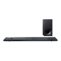
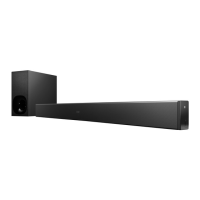
HT-NT3
76
Pin No. Pin Name I/O Description
100 R5PWR5V I
Power supply voltage (+5V) input from the HDMI ASSIGNABLE (INPUT ONLY) IN 1 (VIDEO
1) connector
101 SBVCC5V - Power supply terminal (+5V)
102 VCC33OUT O Power supply (+3.3V) output terminal
103 MHL0_CD0/GPIO0 I/O Not used
104 MHL1_CD1/GPIO1 I/O Not used
105 TX_HPD0 O Hot plug detection signal input from the video processor
106 TXDSDA0 I/O I2C serial data bus terminal Not used
107 TXDSCL0 O I2C serial data transfer clock signal output terminal Not used
108 TX_HPD1 I Hot plug detection signal input from the HDMI ZONE 2 OUT connector
109 TXDSDA1 I/O I2C serial data bus with the HDMI ZONE 2 OUT connector
110 TXDSCL1 O I2C serial data transfer clock signal output to the HDMI ZONE 2 OUT connector
111 APLL12 - Power supply terminal (+1.2V)
112 XTALVCC33 - Power supply terminal (+3.3V)
113 XTALOUT O System clock (27 MHz) output terminal
114 XTALIN I System clock input terminal Not used
115 XTALGND - Ground terminal
116 CVCC12 - Power supply terminal (+1.2V)
117 SS/GPIO2 I/O Not used
118 SCLK/GPIO3 I/O Not used
119 SD0/GPIO4 I/O Not used
120 SD1/GPIO5 I/O Not used
121 WS0_OUT/DR0 O
L/R sampling clock signal output to the DSP1
DSD audio data output to the video processor
122 SCK0/DDCK O
Bit clock signal output to the video processor and DSP1
DSD audio clock signal output to the video processor
123 IOVCC33 - Power supply terminal (+3.3V)
124 SD0_0/DL0 O
Digital audio signal output to the DSP1
DSD audio data output to the video processor
125 MCLK O Master clock signal output to the video processor
126 SD0_1/DR1/GPIO6 O
Digital audio signal output to the DSP1
DSD audio data output to the video processor
127 SD0_2/DL1/GPIO7 O
Digital audio signal output to the DSP1
DSD audio data output to the video processor
128 SD0_3/DR2/GPIO8 O
Digital audio signal output to the DSP1
DSD audio data output to the video processor
129 MUTEOUT/GPIO9 O
HDMI error signal output to the main system controller "H": error
Audio muting control signal output terminal
130 SPDIF0_OUT/DL2 O
S/PDIF audio signal output to the digital audio interface receiver and DSP1
DSD audio data output to the video processor
131 WS0_IN/GPIO11 I/O Not used
132 SCK0_IN/GPIO10 I/O Not used
133 SD0_IN/SPDIF0_IN I Not used
134 SCK1_IN/SCK1_OUT I/O Not used
135 WS1_IN/WS1_OUT I/O Not used
136
SD1_IN/SD1_OUT/
SPDIF1_IN/SPDIF1_
OUT
O S/PDIF audio signal output to the digital audio interface receiver
137 ARC0 I Audio return signal input from the HDMI OUT A ARC connector
138 ARC1 I Audio return signal input terminal Not used
139 CVCC12 - Power supply terminal (+1.2V)
140 TPVDD12 - Power supply terminal (+1.2V)
141 TDVDD12 - Power supply terminal (+1.2V)
142 T1XC– O TMDS clock (negative) output to the HDMI ZONE 2 OUT connector
143 T1XC+ O TMDS clock (positive) output to the HDMI ZONE 2 OUT connector
144 T1X0– O TMDS data (negative) output to the HDMI ZONE 2 OUT connector
145 T1X0+ O TMDS data (positive) output to the HDMI ZONE 2 OUT connector
146 T1X1– O TMDS data (negative) output to the HDMI ZONE 2 OUT connector
147 T1X1+ O TMDS data (positive) output to the HDMI ZONE 2 OUT connector
148 T1X2– O TMDS data (negative) output to the HDMI ZONE 2 OUT connector
149 T1X2+ O TMDS data (positive) output to the HDMI ZONE 2 OUT connector
150 TPVDD12 - Power supply terminal (+1.2V)
 Loading...