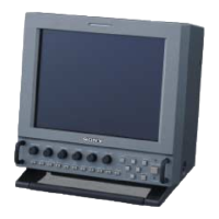
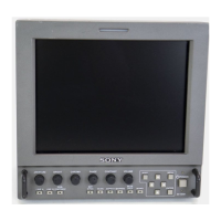
5-11
5-2. IC PIN FUNCTION DESCRIPTION
• MA-324 (H) BOARD IC301 TGA-D2442HA (LCD TIMING GENERATOR)
Pin No. Pin Name I/O Description
1 HDN O
Pulse output for the phase comparator Not used (open)
2 VSS —
Ground terminal
3CKI2I
Clock signal input from the PLL (IC302) (SVGA, VGA)
4 HSYNC I
Horizontal sync signal input from the PLL (IC302)
5 VSYNC I
Vertical sync signal input terminal
6 PEO O
Integrator output terminal for the loop filter (AV) Not used (open)
7PWMI
Integrator input terminal for the loop filter (AV) Not used (open)
8 FPD O
Phase comparator output terminal (AV) Not used (open)
9 RPD O
Phase comparator output terminal (AV) Not used (open)
10 CKO1 O
Clock signal output terminal Not used (open)
11 CKI1 I
Clock signal input terminal Not used (open)
12 VSS —
Ground terminal
13 TC I/O
I/O terminal for the FPD output pulse width adjustment
14 SCTR I
Chip select signal input from the system controller (IC501)
15 SCLK I
Serial data transfer clock signal input from the system controller (IC501)
16 SDAT I
Serial data input from the system controller (IC501)
17 VSS —
Ground terminal
18 to 21 TST1 to TST4 I
Input terminal for the test Not used (open)
22 TST5 I
Input terminal for the test Not used (fixed at “L”)
23 VSS —
Ground terminal
24 VDD —
Power supply terminal (+5V)
25 CKLIM I
Input terminal for the CKI1 (pin qa) input control
“L”: CKI1 input disabled, “H”: CKI1 input enabled Fixed at “L” in this set
26 TST6 I
Input terminal for the test Not used (open)
27 XCLP1 O
Pulse 1 output for the pedestal clamp (negative polarity)
In this set, horizontal sync signal is output for the on screen display controller (IC401)
28 XCLP2 O
Pulse 2 output for the pedestal clamp (negative polarity) Not used (open)
29 PRG O
Pulse output for precharge signal to gamma control IC (IC201) and LCD drive IC (IC202 to 204)
(positive polarity)
30 FRP O
AC drive inversion timing output to the LCD drive IC (IC202 to 204)
31 XFRP O
AC drive inversion timing output terminal (reverse polarity of the FRP e; pin)
Not used (open)
32 VSS —
Ground terminal
33 VDD —
Power supply terminal (+5V)
34 to 37 SHD1 to SHD4 O
Sample hold pulse (1 to 4) output terminal (for driver/positive polarity) Not used (open)
38 VSS —
Ground terminal
39 to 41 SH1 to SH3 O
Sample hold pulse (1 to 3) output terminal (for high voltage-proof SH/positive polarity)
Not used (open)
42 VSS —
Ground terminal
43 to 47 SH4 to SH8 O
Sample hold pulse (4 to 8) output terminal (for high voltage-proof SH/positive polarity)
Not used (open)
48 VDD —
Power supply terminal (+5V)
49 RGT O
Left-right inversion distinguishing signal output to the L & R LCD units “L”: left, “H”: right
50 XRGT O
Left-right inversion distinguishing signal output terminal (reverse polarity of the RGT rl pin)
“L”: right, “H”: left Not used (open)
51 MODE3 O
Mode changes signal output to the L & R LCD units
52 VSS —
Ground terminal
w
w
w
.
x
i
a
o
y
u
1
6
3
.
c
o
m
Q
Q
3
7
6
3
1
5
1
5
0
9
9
2
8
9
4
2
9
8
T
E
L
1
3
9
4
2
2
9
6
5
1
3
9
9
2
8
9
4
2
9
8
0
5
1
5
1
3
6
7
3
Q
Q
TEL 13942296513 QQ 376315150 892498299
TEL 13942296513 QQ 376315150 892498299
http://www.xiaoyu163.com
http://www.xiaoyu163.com