3-16
5. Setting up Input Signals
(1) Video Signal
In adjusting this set, video signals obtained from the pattern
generator are used, and therefore these video output signals
must satisfy the specification. Connect the oscilloscope to the
VIDEO IN terminal, and confirm that the sync signal ampli-
tude of video signals is approximately 286 mV, the amplitude
of video part is approximately 714 mV, burst signal amplitude
is approximately 286 mV and flat, and the level ratio of burst
signal to “red” signal is 0.30 : 0.705.
• When color bar signals are entered
(2) PC Signal (RGB signal)
SECTION 3
ELECTRICAL ADJUSTMENTS
Precautions on adjustment:
1. Perform the adjustment in the given order.
2. Power supply voltage: DC 8.4 V
3. Equipment required
Electrical adjustment requires the following measuring equip-
ment.
(1) Oscilloscope: 2 phenomena, band 30 MHz or more, with de-
lay mode (use 10 : 1 probe unless otherwise specified)
(2) Pattern generator
(3) Regulated power supply
(4) Digital voltmeter
(5) Frequency counter
(6) Connector for adjustment
(7) Kent paper (for Power Saving Sensor adjustment)
4. Measurement points for adjustment are located at CN1003 on
the YC-148 (H) board and at CN206 on the MA-324 (H) board.
The pin No. and signal name of CN1003 and CN206 are listed
below.
• YC-148 (H) board, CN1003
• MA-324 (H) board, CN206
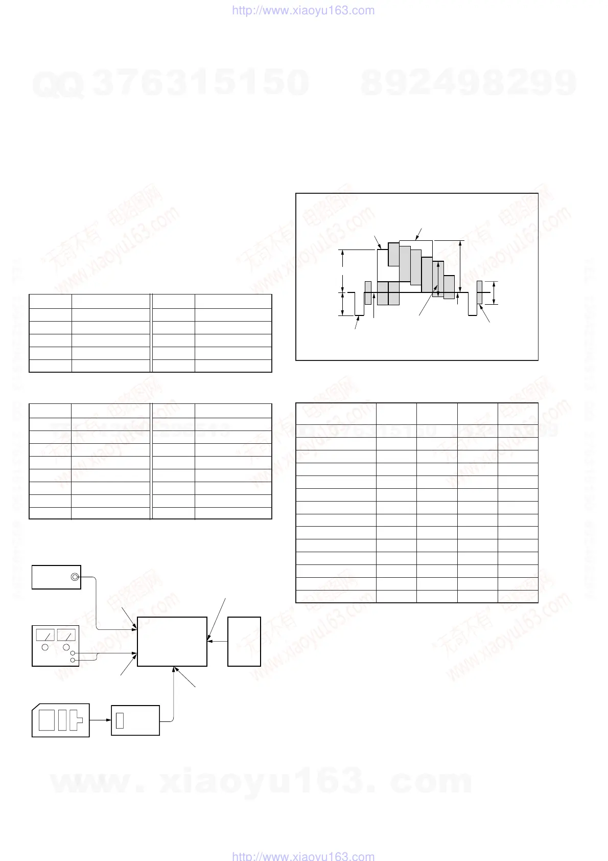
Preparation:
Connect electrical blocks as shown below.
Pin No. Signal Name
1GND
2GND
3GND
4 4FSC
5GND
Pin No. Signal Name
6 GND
7 Y OUT
8 VIDEO G
9 N.C
10 GND
Pin No. Signal Name
1 SIG R 1
2A
3 SIG G 1
4 POWER SW
5 SIG B 1
6 ENTER
7 INT H
8 VIDEO/XPC IN
Pin No. Signal Name
9 GND
10 GND
11 B
12 COM R
13 C
14 COM L
15 SIG CEN
16 P SIG B
Fig. 3-1. Pattern generator's color bar signals
Signal mode
H V HDISP VDISP
(kHz) (Hz) (dots) (dots)
PC98 24.82 56.41 640 400
VGA-TEXT 31.47 70.08 640 362
VGA-GRAP 31.47 59.94 640 480
VGA72 37.86 72.82 640 480
VGA75 37.50 74.99 640 480
MAC13’ 35.00 66.67 640 480
VGA85 43.27 85.01 640 480
SVGA56 35.16 56.26 800 600
SVGA60 37.88 60.32 800 600
SVGA72 48.08 72.19 800 600
SVGA75 46.88 75.01 800 600
SVGA85 53.68 85.07 800 600
MAC16’ 49.73 74.55 832 624
XGA60 48.36 59.99 1024 768
pattern
generator
Set PC
DC 8.4V
DC IN 8.4 V jack
DD-107 (H) board
(J701)
S-VIDEO jack
JK-136 (H) board
(J1401)
RGB terminal
MA-324 (H) boar
(J101)
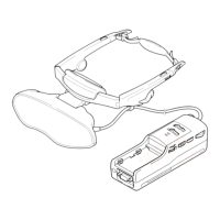
Adjusting Remote
Commander
RM-95
(J-6082-053-B)
Extension cable
(J-6082-291-A)
MA-324 (H) board
CN501
White (75%)
535
±
3 mV
714
±
3 mV
286
±
3 mV
Red
672
±
3 mV
Pedestal
Horizontal sync signal
Black
Burst signal
(to be flat)
286
±
3 mV
White (100%)
w
w
w
.
x
i
a
o
y
u
1
6
3
.
c
o
m
Q
Q
3
7
6
3
1
5
1
5
0
9
9
2
8
9
4
2
9
8
T
E
L
1
3
9
4
2
2
9
6
5
1
3
9
9
2
8
9
4
2
9
8
0
5
1
5
1
3
6
7
3
Q
Q
TEL 13942296513 QQ 376315150 892498299
TEL 13942296513 QQ 376315150 892498299
http://www.xiaoyu163.com
http://www.xiaoyu163.com