5-185-18 E
*1 Bass boost control
012
DBB MID ON (pin rl)
“L” “H” “L”
DBB NORM ON (pin t;)
“H” “L” “L”
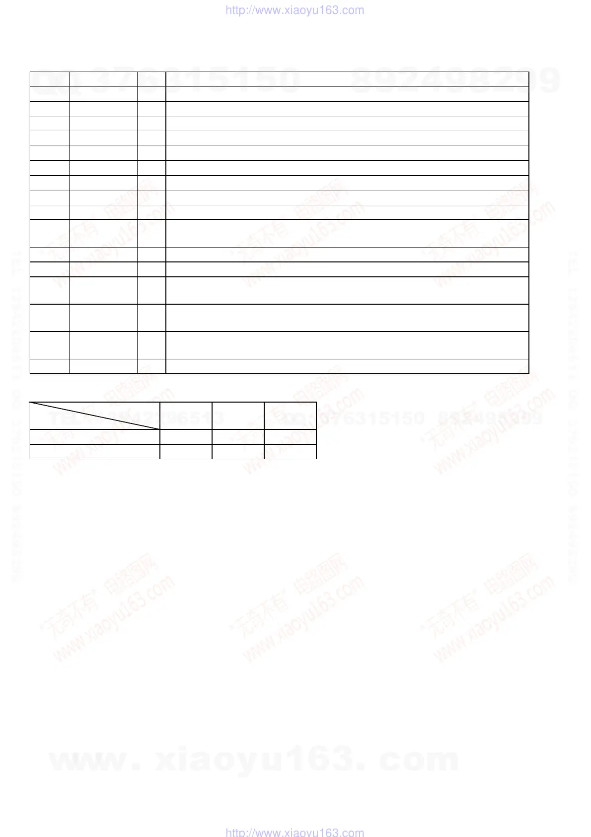
Terminal
Mod
Pin No. Pin Name I/O Description
84 DC IN MON I
Connection detect signal input of the DC IN jack (J701) “L”: DC IN jack connected
85 BATT IN MON I
Connection detect signal input of the battery pack “L”: battery pack connected
86, 87 VDD —
Power supply terminal (+5V)
88 VSS —
Ground terminal
89 V MUTE O
Video mute on/off control signal output terminal “H”: mute on
90 AU MUTE O
Audio mute on/off control signal output to the headphone amplifier (IC151) “H”: mute on
91 POWER LED O
LED drive signal output of the POWER ON indicator (D901-1 (green)) “H”: LED on
92 CHARGE LED O
LED drive signal output of the CHARGE indicator (D902) “H”: LED on
93 BL ON O
Back light unit on/off control signal output terminal “H”: back light on
94 DD MAIN O
Main system power on/off control signal output to the DC/DC converter (IC701, 703)
“H”: power on
95 CHARGE ON O
Charging on/off control signal output terminal “H”: charge on
96 BATT CHK O
Control signal output to the battery check circuit “H” active
97 BATT CONT O
Power supply (DC IN jack/battery pack) selection signal output terminal
“L”: DC IN jack selection, “H”: battery pack selection
98 DD SENSOR O
Sensor system and fan motor power on/off control signal output to the DC/DC converter (IC701)
“H”: power on
99
PC/XVIDEO
CONT
O
Picture input signal selection control signal output to the PC/video RGB selector (IC131)
“L”: video, “H”: PC
100 VIDEO 5V ON O
Video system power on/off control signal output terminal “H”: power on
w
w
w
.
x
i
a
o
y
u
1
6
3
.
c
o
m
Q
Q
3
7
6
3
1
5
1
5
0
9
9
2
8
9
4
2
9
8
T
E
L
1
3
9
4
2
2
9
6
5
1
3
9
9
2
8
9
4
2
9
8
0
5
1
5
1
3
6
7
3
Q
Q
TEL 13942296513 QQ 376315150 892498299
TEL 13942296513 QQ 376315150 892498299
http://www.xiaoyu163.com
http://www.xiaoyu163.com